A Time Grating Linear Displacement Sensor

A linear displacement and sensor technology, applied in the direction of instruments, measuring devices, electrical devices, etc., can solve problems affecting the measurement accuracy of sensors, complex sensor structures, and complicated winding methods, and achieve simple structure, easy productization, and low cost Effect

Active Publication Date: 2019-04-02
CHONGQING UNIV OF TECH
View PDF8 Cites 0 Cited by
  • Summary
  • Abstract
  • Description
  • Claims
  • Application Information

AI Technical Summary

Problems solved by technology

However, the winding methods of the excitation coil and the induction coil of the existing several types of time grating linear displacement sensors are complicated, which makes the structure of the sensor complex and difficult to realize; and the accuracy of the relative arrangement of the excitation coil and the induction coil of the sensor , the number of turns and the performance consistency of the magnetizer will also directly affect the measurement accuracy of the sensor

Method used


Image

  • A Time Grating Linear Displacement Sensor
  • A Time Grating Linear Displacement Sensor
  • A Time Grating Linear Displacement Sensor

Examples


Embodiment 1

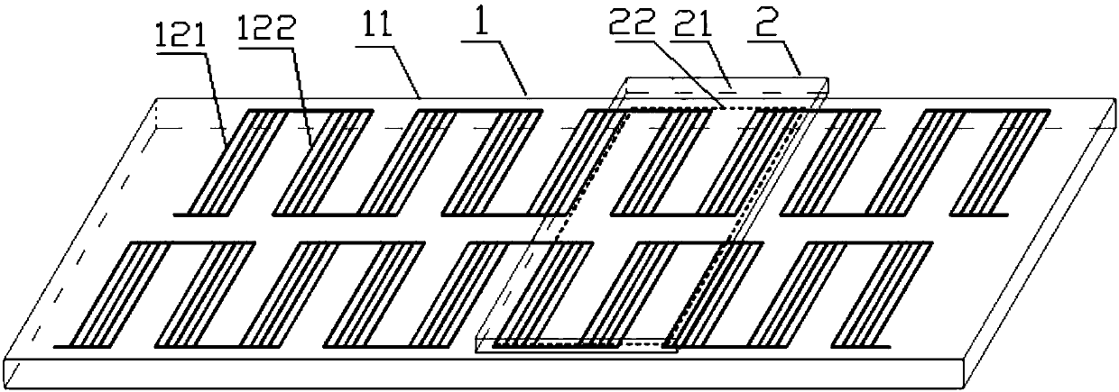
[0039] Embodiment 1: as figure 1 , figure 2 , image 3 The time grating linear displacement sensor shown includes a fixed scale 1 and a moving scale 2, and the moving scale 2 is directly opposite to the fixed scale 1 in parallel with a gap of 0.1 mm.

[0040] The fixed length 1 is made up of the fixed length base 11 and the excitation unit fixed on the surface of the fixed length base 11. The fixed length base 11 is a rectangular parallelepiped magnetic material base, and the long side direction of the fixed length base 11 is the measurement direction (i.e. The direction of motion of the ruler), the excitation unit is a printed circuit board with two insulating layers and an excitation coil layer, the surface area of ​​the fixed-length substrate 11 is greater than the coverage area of ​​the excitation coil layer, and there is a margin in four directions.

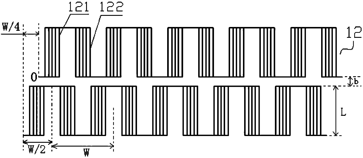
[0041] Such as figure 2 As shown, the excitation coil layer is composed of two identical and parallel excitation coil...

Embodiment 2

[0050] Embodiment 2: Most of the structures of the time grating linear displacement sensor in this embodiment are the same as in Embodiment 1, except that the excitation unit is a printed circuit board with 4 insulating layers and 3 above-mentioned excitation coil layers, 4 An insulating layer and three excitation coil layers are arranged at intervals along the direction perpendicular to the surface of the fixed-length substrate 11, and the three excitation coil layers are connected in parallel with each other through via hole wiring, which improves the magnetic field strength of the fixed length; the induction unit has A printed circuit board with 4 insulating layers and 3 above-mentioned induction coil layers, the 4 insulating layers and 3 induction coil layers are arranged at intervals along the direction perpendicular to the surface of the moving scale base 21, and the 3 induction coil layers are connected through via holes The way of connecting each other in series improve...

Embodiment 3

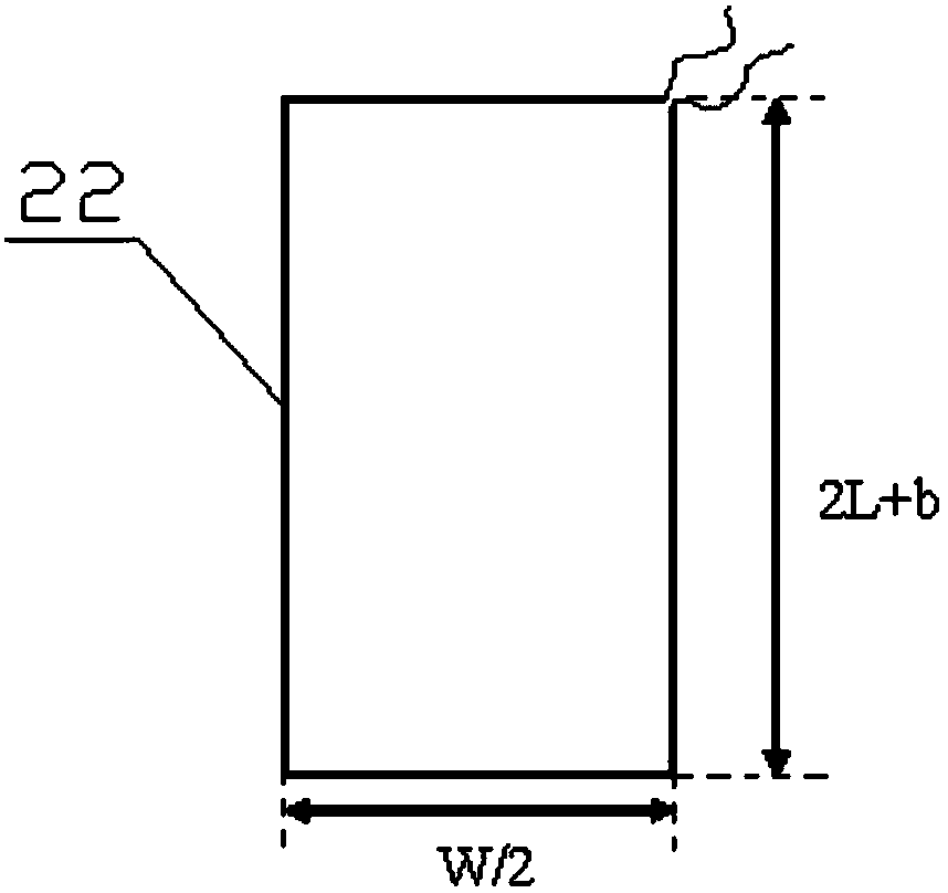
[0051] Embodiment 3: as Figure 4 As shown, most of the structures of the time grating linear displacement sensor in this embodiment are the same as in Embodiment 1, the difference is that the induction coil layer is composed of a first induction coil line array arranged on a printed circuit board, and the first induction coil An induction coil line array is composed of two identical second rectangular coils 23 connected in series along the measuring direction. The width of each second rectangular coil 23 along the measuring direction is W / 2-c, and the length perpendicular to the measuring direction is 2L+ b, two second rectangular coils 23 are located on one wiring layer, the center distance is W / 2 and the winding direction is opposite, and the lead-out wires of the two second rectangular coils 23 are located on another wiring layer, where c represents two adjacent Minute spacing between the second rectangular coils 23 .

[0052] The two excitation coil arrays 12 are respect...


PUM


Abstract

The invention discloses a time grating linear displacement sensor, which comprises a fixed length and a moving ruler. The fixed length is composed of a magnetically conductive fixed-length base and an excitation unit arranged on the fixed-length base. The excitation unit includes an insulating layer and an excitation coil layer. The excitation coil layer is composed of two excitation coil arrays. The excitation coil array is composed of m identical wire groups arranged in series along the measurement direction. The forward and reverse wire units in the wire group are composed of n straight wire segments according to It is composed of certain rules in parallel; the moving scale is composed of a magnetically conductive moving scale base and an induction unit arranged on the moving scale base. The induction unit includes an insulating layer and an induction coil layer. The induction coil layer is composed of rectangular coils that meet certain wiring rules. The sensor can simplify the structure of the sensor and make the sensor easy to be commercialized under the condition of ensuring high resolution.

Description

technical field [0001] The invention belongs to the field of precision displacement measurement, and in particular relates to a time grating linear displacement sensor. Background technique [0002] Linear displacement measurement is the most basic geometric quantity measurement. Precision linear displacement measurement mainly uses linear displacement sensors, such as gratings, magnetic gratings, capacitive gratings, etc., which obtain the displacement by counting the grid lines divided by space. The characteristic is to use the space ultra-precise scribe line of the grid line to meet the resolution requirements of small displacements. In order to further improve the resolution, it can only rely on complex electronic subdivision, so that the system structure is complicated, the cost is high, and the resistance is high. Poor interference ability, highly susceptible to pollution. [0003] The time grating linear displacement sensor is a sensor based on the principle of elect...

Claims


Application Information

Patent Timeline
Patent Type & Authority Patents(China)
IPC IPC(8): G01B7/02
CPCG01B7/02
Inventor 武亮彭东林汤其富徐是鲁进陈锡侯
Owner CHONGQING UNIV OF TECH
Why Eureka
Try Eureka