Vehicle with fuel filler line and rear compound crank arrangement

A technology combining tie rod shafts and injection pipes, applied in the direction of the arrangement combined with the fuel supply of internal combustion engines, power plants, vehicle components, etc., to achieve the effect of simple extension routes and compact structures

Active Publication Date: 2012-12-26
GM GLOBAL TECH OPERATIONS LLC
View PDF6 Cites 0 Cited by
  • Summary
  • Abstract
  • Description
  • Claims
  • Application Information

AI Technical Summary

Problems solved by technology

The potential for improving driving comfort is not fully exploited in today's vehicles with combined tie-rod axles, since the available vibration amplitude of the combined tie-rod axle is an indicator of the achievable driving comfort

Method used


Image

  • Vehicle with fuel filler line and rear compound crank arrangement
  • Vehicle with fuel filler line and rear compound crank arrangement
  • Vehicle with fuel filler line and rear compound crank arrangement

Examples


Embodiment Construction

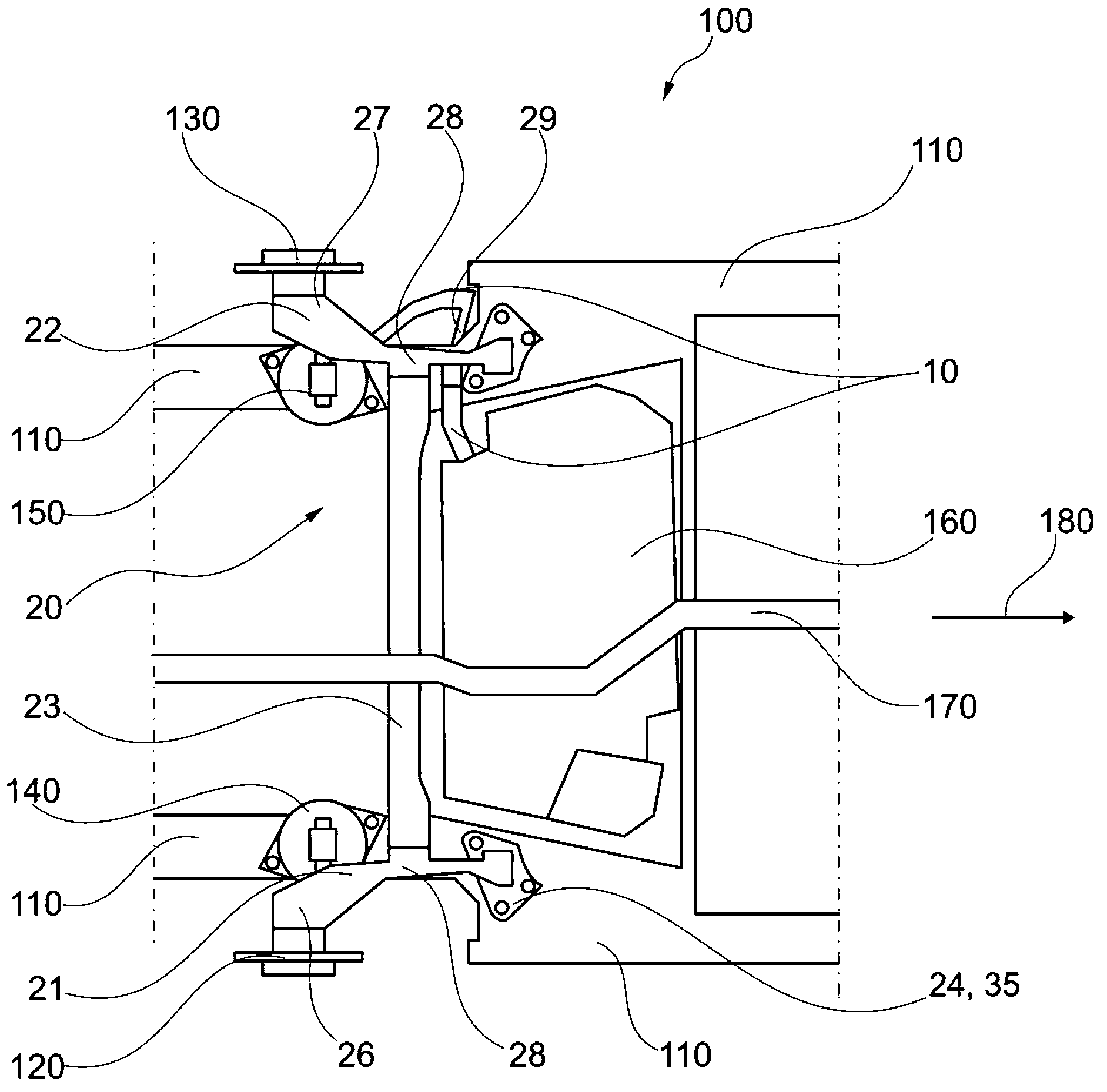
[0035] figure 1 A partial bottom view of a possible embodiment of the rear part 100 of a vehicle in the area of ​​the combined tie rod shaft 20 of the rear part 100 is shown.

[0036] The rear part 100 has a body structure 110, and the combined tie rod shaft 20 is rotatably supported on the body structure 110, especially in a vertical direction of the rear part 100. To this end, the combined tie rod shaft 20 has connecting elements 24, 25, and the combined tie rod shaft 20 is connected to the vehicle body 110 by means of the connecting elements 24, 25. The connecting elements 24, 25 are, for example, so-called bushes, in particular A bushes.

[0037] The connecting elements 24, 25 are arranged on the two longitudinal rods 21, 22 of the combined rod shaft 20, wherein the connecting element 24 is assigned to the longitudinal rod 21 and the connecting element 25 is assigned to the longitudinal rod 22. The connecting elements 24, 25 are preferably arranged at the ends of the longitudi...


PUM


Abstract

The invention relates to an arrangement for the rear end 100 of a motor vehicle with a fuel filler line 10 and a compound crank 20 having two trailing arms 21, 22 and a cross member 23 connecting the trailing arms with each other. The trailing arms 21, 22 are pivotably supported in the direction of their longitudinal axis on their one end area by means of a connection element 24, (25a see fig 3) on the body shell 110 of the vehicle, and have on their other end area a holder 26, 27 for a wheel bearing unit 120, 130. Provision is made that the filler line 10 crosses at least one of the trailing arms 21, 22 in the area between a connection site 28 for the cross member 23 and the connection element (25a ). The invention further relates to a compound crank 20 for the rear end 100 of a motor vehicle, a rear end 100 and a vehicle. The arrangement is suited to compactness and is consistent with ride comfort without the fuel filler line 10 impeding the path of the crank.

Description

Technical field [0001] The present invention relates to a device for the rear of an automobile with a fuel injection pipe and a combined tie rod shaft. The combined tie rod shaft has two longitudinal tie rods and a cross beam connected to the longitudinal tie rod. The longitudinal tie rod is on its longitudinal axis. One end region in the direction is each rotatably supported on the body of the motor vehicle by means of connecting elements, and the other end region has a bracket for a wheel or a wheel brake in each case. The invention also relates to a combined tie rod shaft, an injection pipe, a rear part of a vehicle and an automobile. Background technique [0002] Modern cars increasingly have combined tie rod axles (also called "combined tie rod rear axles" or "torsion beam suspensions") in compact cars. The combined tie rod shaft is usually composed of two longitudinal tie rods connected to each other by a cross beam (also referred to as a "transverse support" or a "torsion...

Claims


Application Information

Patent Timeline
Patent Type & Authority Applications(China)
IPC IPC(8): B60K15/063B60G21/055
CPCB60G2204/201B60G21/051B60K15/04B60K2015/0638B60K2015/0474
Inventor J.西贝内克
Owner GM GLOBAL TECH OPERATIONS LLC
Why Eureka
Try Eureka