Charging device

a charging device and charging circuit technology, applied in the direction of electric power transfer ac network, parallel operation of dc source, transportation and packaging, etc., can solve the problems of fine short circuit, difficult integration and miniaturization, and reduced usable charging capacity of series-connected battery cells, so as to reduce the effect of common mode noise generated between electric accumulator cells and rectangular wave power sources and the reduction of transient curren

Inactive Publication Date: 2008-04-10
HONDA MOTOR CO LTD
View PDF5 Cites 30 Cited by
  • Summary
  • Abstract
  • Description
  • Claims
  • Application Information

AI Technical Summary

Benefits of technology

[0022]According to a seventh aspect of the present invention, it is preferred that in the charging device according to the fourth or sixth aspect of the present invention, one electrode of any one of the electric accumulator cells has the same potential as a reference potential of the rectangular wave power source. With such a configuration, the effect of the common mode noise generated between the electric accumulator cells and the rect

Problems solved by technology

In other words, since the series-connected battery cells early reach the charging upper limit or charging lower limit, usable charging capacity of the series-connected battery cells is actually decreased.
Further, as a failure of the battery, a fine short circuit may occur.
Further, in the technique that uses the transformer to achieve insulation, it will be difficult to achieve integration and miniaturization since the t

Method used


Image

  • Charging device
  • Charging device
  • Charging device

Examples


first embodiment

[0036]A charging device according to a first embodiment of the present invention will be described below with reference to the attached drawings.

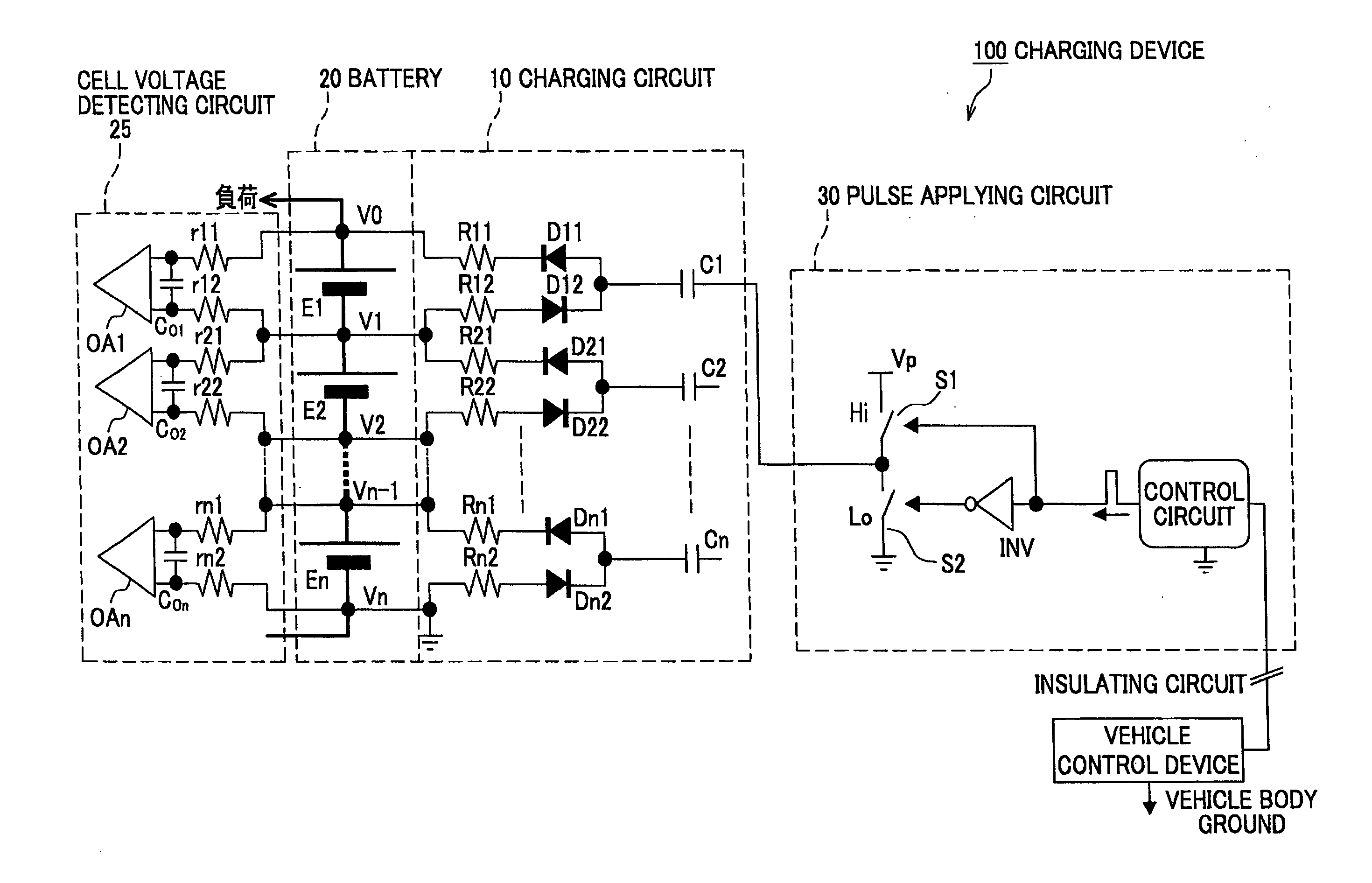
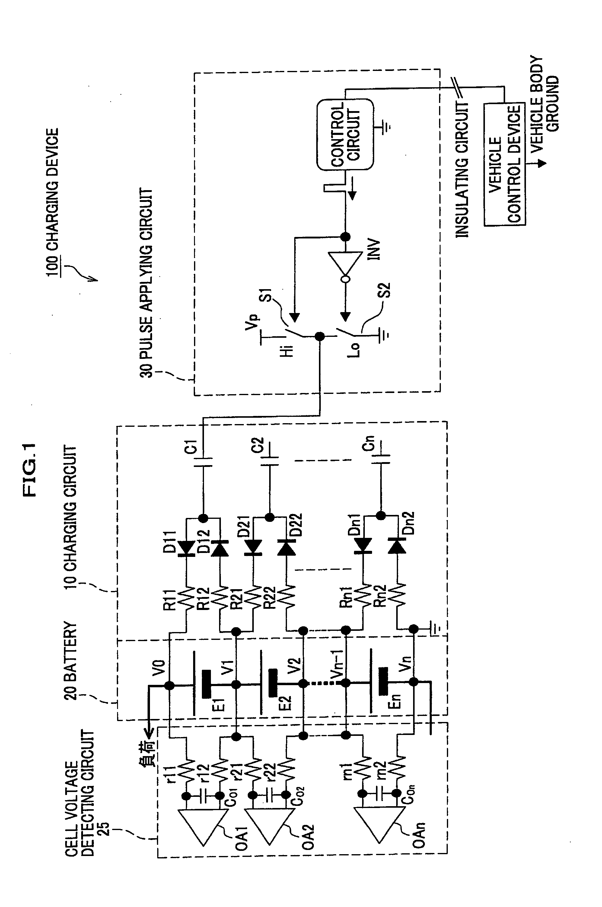
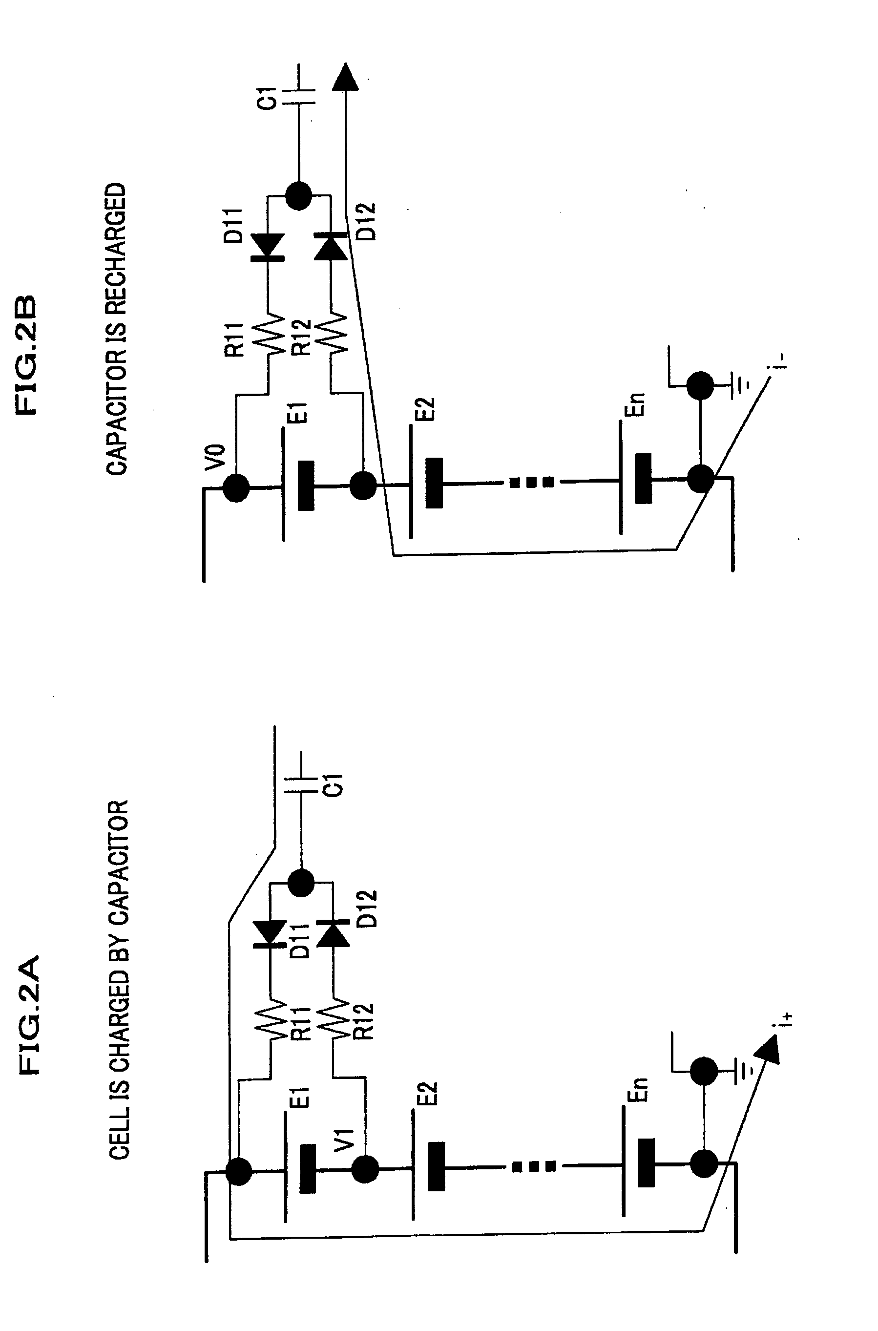
[0037]A charging device 100 shown in FIG. 1 includes a battery 20 formed by connecting n battery cells (electric accumulator cells) E1, E2, . . . , En in series, a charging circuit 10 for charging each of the battery cells (electric accumulator cells) E1, E2, . . . , En, a pulse applying circuit 30 which is a periodical power source (a rectangular wave power source) for generating a rectangular wave to drive the charging circuit 10, and a cell voltage detecting circuit 25 for measuring the voltage of each of the battery cells (the electric accumulator cells) E1, E2, . . . , En. Incidentally, the battery 20 is connected to a load. Further, the pulse applying circuit 30 is connected through an insulating circuit, to a vehicle control device which is grounded to a vehicle body. A reference potential of the battery 20, the charging circuit 10 a...

second embodiment

[0050]According to the first embodiment, in order to charge the battery cell E1, the other battery cells E2, E3, . . . , En are charged and discharged. However, there is also a configuration in which only the battery cell E1 is charged according to a second embodiment of the present invention. A charging device according to the second embodiment will be described below with reference to FIG. 5.

[0051]A charging device 150 includes the cell voltage detecting circuit 25, the battery 20, a charging circuit 15, and a pulse applying circuit 35. The cell voltage detecting circuit 25 and the battery 20 will not be described since they have the same configuration as that of the first embodiment. Only the charging circuit 15 and the pulse applying circuit 35 will be described below. Incidentally, similar to the first embodiment, the pulse applying circuit 35 is connected to the negative electrode, which serves as the reference potential, of battery cell En.

[0052]The charging circuit 15 charge...


PUM


Abstract

A charging device has an electric accumulator (20) formed by a plurality of series-connected electric accumulator cells (E1, E2, . . . , En), one electrode of any one of the electric accumulator cells being used as a reference potential of the electric accumulator (20); at least one capacitor (C1) having one end fixed to the potential of one electrode of each of the electric accumulator cells (E1, E2, . . . , En) or fixed to the potential of the other electrode of any one of the electric accumulator cells (E1, E2, . . . , En) through a rectifying means (D11, D12); and a periodical power source (30) connected between the capacitor (C1) and the reference potential of the electric accumulator to generate repetitive signals.

Description

CROSS-REFERENCE TO RELATED APPLICATION(S)[0001]This application claims the foreign priority benefit under Title 35, United States Code, §119 (a)-(d), of Japanese Patent Application No. 2006-272504 filed on Oct. 4, 2006 in the Japan Patent Office, the disclosure of which is herein incorporated by reference in its entirety.BACKGROUND OF THE INVENTION[0002]1. Field of the Invention[0003]The present invention relates to a charging device for charging an electric accumulator formed by a plurality of series-connected electric accumulator cells.[0004]2. Description of the Related Art[0005]More and more electric vehicles such as electric cars, fuel-cell-powered cars and hybrid cars have been putting into practical use in order to achieve low emissions, low noise and low gasoline consumption. Such electric vehicles are each equipped with a high voltage battery for driving a running motor. The high voltage of the high voltage battery is obtained by connecting a plurality of low voltage batter...

Claims


Application Information

Patent Timeline
IPC IPC(8): H02J7/00H02J7/02
CPCH02J7/0019H02J7/1423H02J7/242Y02T10/7055Y02T10/7005Y02T10/7022H02J7/345H02J7/24Y02T10/70
Inventor OHNUKI, YASUMICHI
Owner HONDA MOTOR CO LTD
Why Eureka
Try Eureka