Data recording system with servo pattern having pseudo-random binary sequences

a data recording and binary sequence technology, applied in the field of data recording systems, can solve the problems of repeatable errors in the servo position information obtained, two distinct alignment problems, and track misregistration (tmr)

Inactive Publication Date: 2005-11-22
WESTERN DIGITAL TECH INC
View PDF1 Cites 31 Cited by
  • Summary
  • Abstract
  • Description
  • Claims
  • Application Information

AI Technical Summary

Benefits of technology

[0007]In a magnetic recording disk drive implementation of the invention, the disk drive includes a variable gain amplifier that amplifies the recorded signal read by the head, a TID detector, an actuator that moves the head to the desired track and maintains it on the desired track, and a servo position information decoder that receives the first PRBS and second PRBS read by the head when the servo pattern passes beneath the head. The decoder includes a first correlator for the first PRBS and a second correlator for the second PRBS. Each correlator is matched to a single period of its associated PRBS and outputs a single dipulse each time its associated PRBS repeats. The difference in amplitude of the dipulses from the two correlators represents the head position signal sent by the decoder to the disk drive actuator. The correlator dipulse having the larger amplitude controls the variable gain amplifier and the timing of the TID detector.

Problems solved by technology

Alignment of each individual track with its neighbors is a key problem in writing the servo pattern.
Two distinct alignment problems may occur.
Track misregistration (TMR) occurs due to an error in the radial position of the head during servowriting.
This translates to a repeatable error in the servo position information obtained from the servo pattern.
As the recording density increases the servo pattern features become correspondingly smaller and circumferential misalignment becomes more of a problem.

Method used


Image

  • Data recording system with servo pattern having pseudo-random binary sequences
  • Data recording system with servo pattern having pseudo-random binary sequences
  • Data recording system with servo pattern having pseudo-random binary sequences

Examples


Embodiment Construction

[0024]Description of the Prior Art

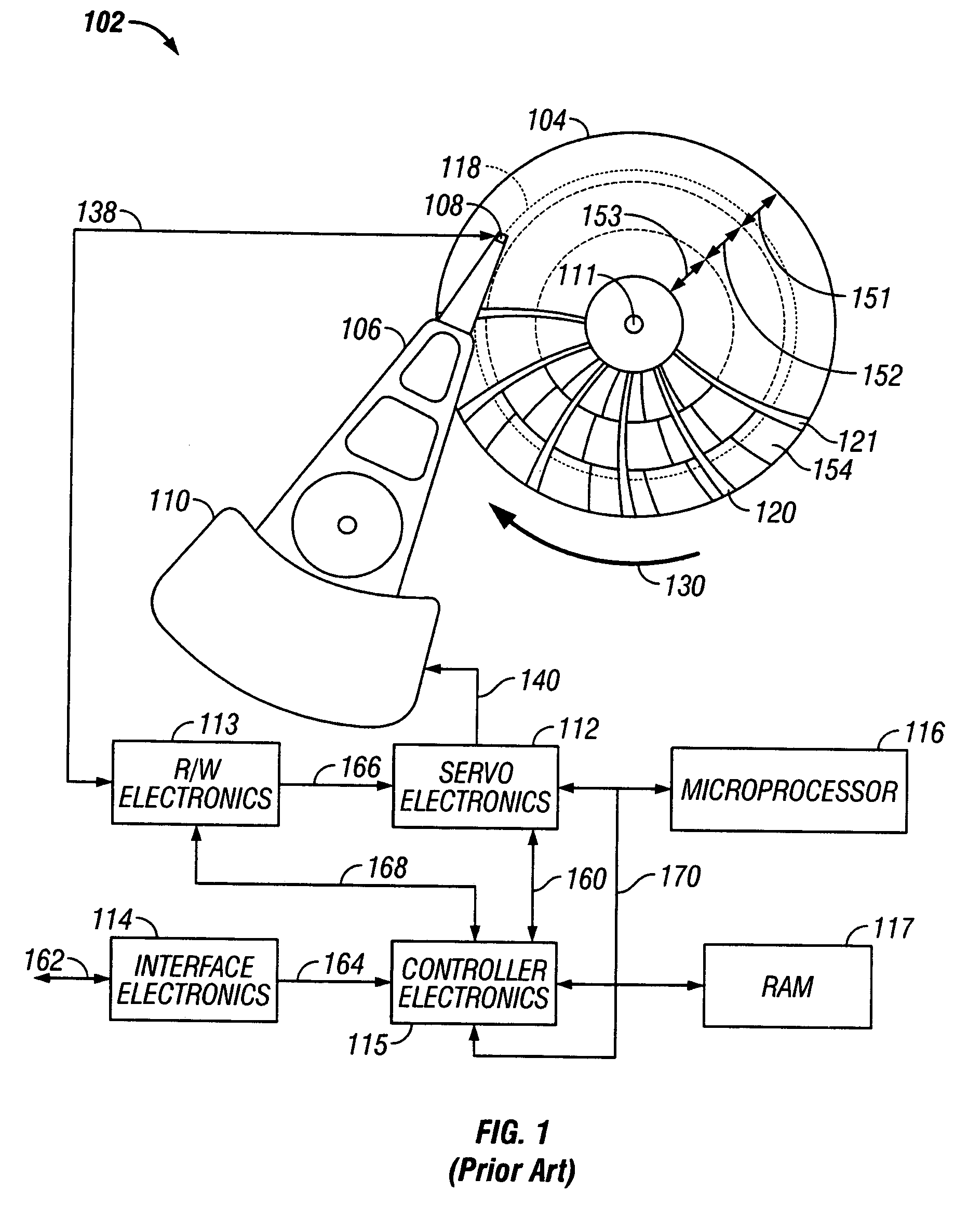
[0025]FIG. 1 is a block diagram of a disk drive of the type usable with the present invention. The disk drive depicted is one that is formatted using a fixed-block “headerless” architecture with sector servo and zone-bit recording (ZBR).

[0026]The disk drive, designated generally as 102, includes data recording disk 104, actuator arm 106, data recording transducer 108 (also called a head, recording head or read / write head), voice coil motor 110, servo electronics 112, read / write electronics 113, interface electronics 114, controller electronics 115, microprocessor 116, and RAM 117. The recording head 108 may be an inductive read / write head or a combination of an inductive write head with a magnetoresistive read head. Typically, there are multiple disks stacked on a hub that is rotated by a disk motor, with a separate recording head associated with each surface of each disk. Data recording disk 104 has a center of rotation 111 and is rotated in direct...


PUM

PropertyMeasurementUnit
densityaaaaaaaaaa
linear densityaaaaaaaaaa
magnetoresistiveaaaaaaaaaa

Abstract

A data recording system, such as a magnetic recording hard disk drive, has a recording medium in which the data tracks have pseudo-random binary sequences for the servo information used to control the position of the recording head. A first pseudo-random binary sequence (PRBS) and a second PRBS identical to the first PRBS but shifted by a portion of the period of the first PRBS are located between the track boundaries in alternating tracks in a first region of the servo pattern and between the track centers in alternating tracks in a second region spaced along the track from said first region. A servo decoder has two correlators, one for each PRBS. Each correlator outputs a dipulse when its PRBS repeats. The difference in amplitude of the dipulses represents the head position signal. The dipulses also control the amplifier for the signal read back by the head and the timing of the track identification (TID) detector.

Description

RELATED APPLICATION[0001]This application is related to concurrently filed application Ser. No. 10 / 845,813 titled DATA RECORDING MEDIUM WITH SERVO PATTERN HAVING PSEUDO-RANDOM BINARY SEQUENCES. Both applications are based on a common specification, with this application having claims directed to a data recording system and having claims directed to a data recording medium.TECHNICAL FIELD[0002]This invention relates generally to data recording systems, such as magnetic recording hard disk drives, and more particularly to pre-recorded servo patterns and servo positioning systems to locate and maintain the read / write heads on the data tracks.BACKGROUND OF THE INVENTION[0003]Magnetic recording hard disk drives use a servo-mechanical positioning system to hold the read / write head on the desired data track and to seek from track to track as required to perform read and write operations. Special “servo” information is written in fields in circumferentially-spaced servo sectors in each of t...

Claims


Application Information

Patent Timeline
Patent Type & Authority Patents(United States)
IPC IPC(8): G11B20/10G11B20/14G11B20/12G11B5/55G11B5/596G11B21/10
CPCG11B5/5526G11B5/59688G11B20/1217G11B20/1403G11B2020/1232G11B2020/1238G11B2020/1287G11B2220/2516
Inventor BANDIC, ZVONIMIR Z.NEW, RICHARD M. H.WILSON, BRUCE ALEXANDER
Owner WESTERN DIGITAL TECH INC
Why Eureka
Try Eureka