
Power transmission belt and method

a technology of transmission belt and transmission belt, which is applied in the direction of gearing, other domestic objects, mechanical equipment, etc., can solve the problems of composition degradation, reduced effective elastic modulus,

Inactive Publication Date: 2003-07-10
THE GATES CORP
View PDF13 Cites 29 Cited by
  • Summary
  • Abstract
  • Description
  • Claims
  • Application Information

AI Technical Summary

Benefits of technology

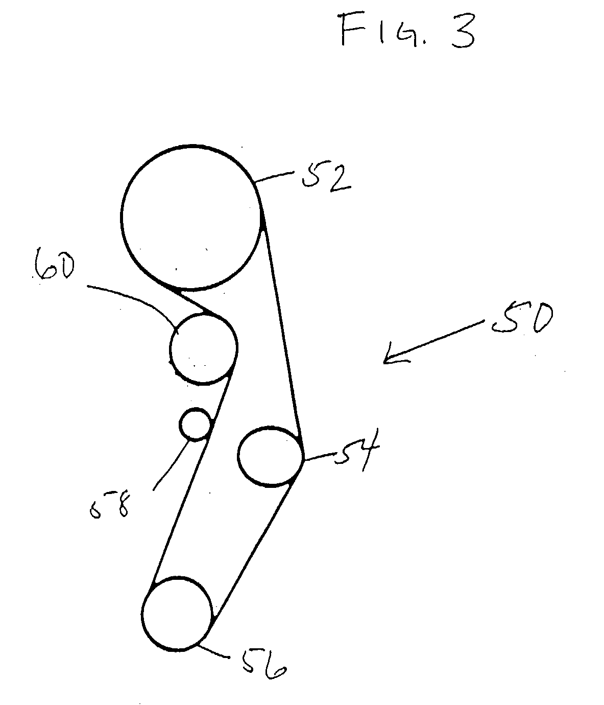
[0089] It has been found that timing belts constructed in accordance with one or more embodiments of the present invention provide significant improvement in one or more specific performance areas when utilized to drive a camshaft in an internal combustion engine, and particularly in automotive internal combustion engines. In particular, these belts have been found to significantly reduce undesirable angular vibration of an automotive engine camshaft in relation to an associated crankshaft with engine operation. What is meant by the term "angular vibration" in the present context is that rotational vibration of the camshaft, i.e., vibration of the shaft about it's longitudinal axis; that may be caused for example by any or all of the torsional vibration exhibited by the camshaft resulting from an applied twisting force along its length, or by the free body rotation of the camshaft itself, or by the cyclic- or periodic angular velocity superimposed upon the mean camshaft speed by the non-uniform or non-constant nature of an applied drive torque. Moreover, at certain crankshaft speeds for a given engine, larger amplitudes of such camshaft angular vibration generally occur due to the excitation of one or more drive system resonant frequencies at such speeds.

Problems solved by technology

This is distinguishable from the elastic modulus of such composition in its final form upon, about and within the interstices of a tensile cord, wherein any residual water from the latex or other sources may, if not substantially driven off in the processing steps, result in a decreased effective elastic modulus of the composition; or wherein exposure of the treated cord to excessive temperature for prolonged periods may result in degradation of the composition, particularly for those compositions employing low heat-resistant latex, e.g., VP / SBR.

Method used

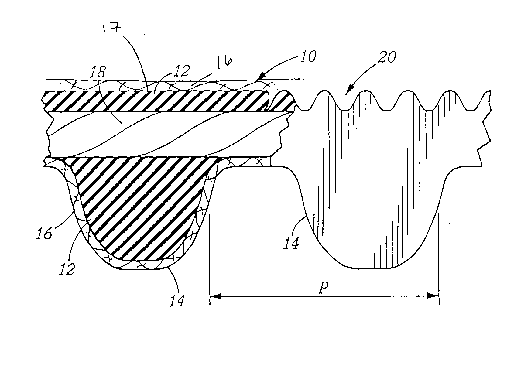
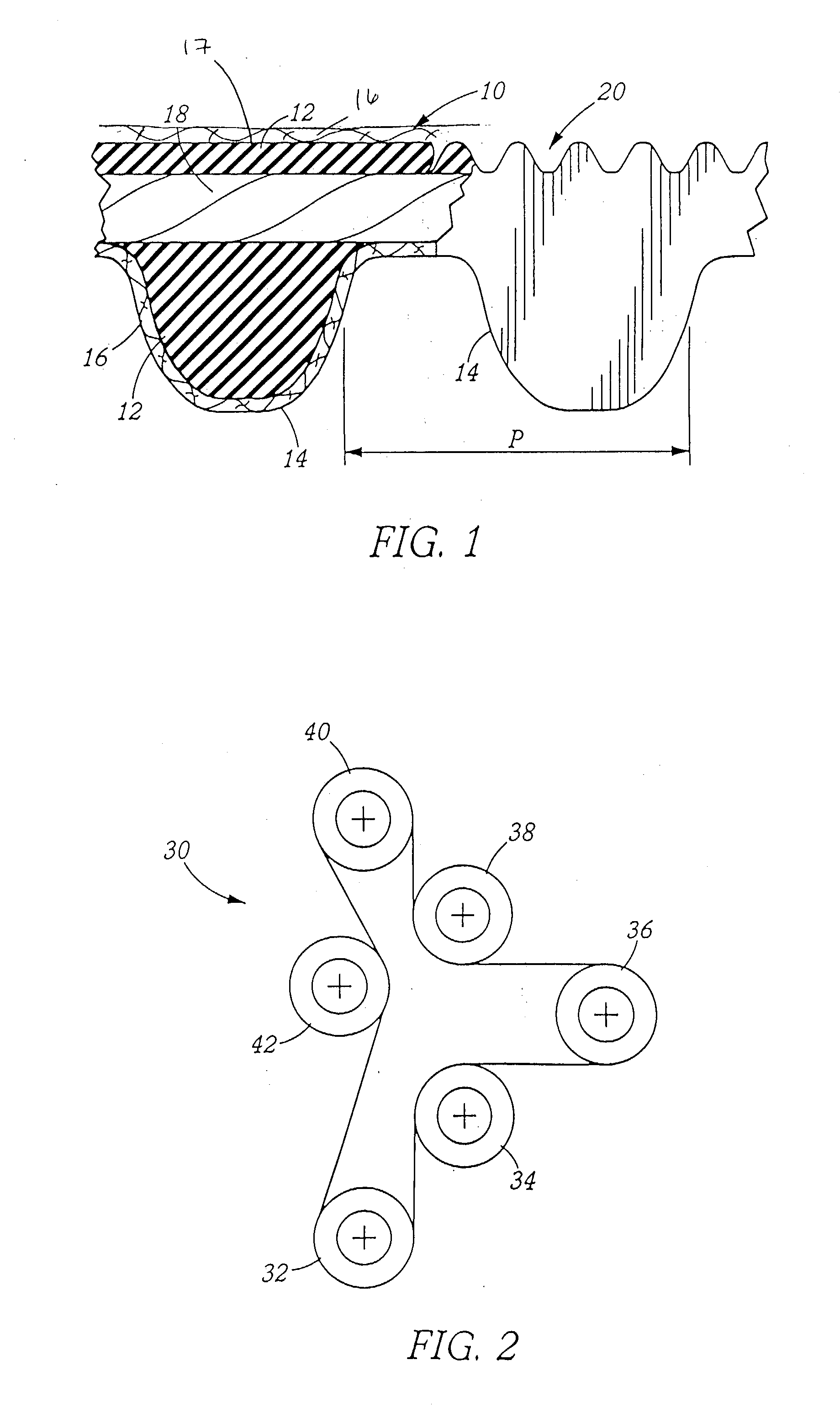

Image

  • Power transmission belt and method
  • Power transmission belt and method
  • Power transmission belt and method

Examples


example 2 example 3 example 4 example 5 example 6

Amount of 0.0 0.0 0.0 4.0 8.0 4.0 Carbon black added to X-HNBR RFL Composition (Wt. %, wet) Elastic 5.7 .times. 10.sup.7 5.7 .times. 10.sup.7 5.7 .times. 10.sup.7 1.0 .times. 10.sup.8 8.2 .times. 10.sup.8 1.0 .times. 10.sup.8 Modulus of RFL film at 20.degree. C. (dynes / cm.sup.2) Elastic 2.2 .times. 10.sup.7 2.2 .times. 10.sup.7 2.2 .times. 10.sup.7 3.5 .times. 10.sup.7 1.6 .times. 10.sup.8 3.5 .times. 10.sup.7 Modulus of RFL film at 100.degree. C. (dyns / cm.sup.2) Average Oven 145.8 145.8 145.8 145.8 145.8 145.8 Temp. Zone 1 (.degree. C.) Average Oven 231.5 267.0 302.5 231.5 231.5 267.0 Temp. Zone 2 (.degree. C.) Cord moisture 7.1% 6.4% 3.3% 15.5% 12.4% 2.4% content (% H.sup.2O) Cord Stiffness 56.4 58.0 -- 73.6 82.4 86.0 (average) (10 unit counter-balance) Belt growth 0.121 0.071 0.104 0.055 0.098 0.093 after 24 hours 0.093 0.093 0.082 0.104 0.087 0.082 (%) Belt growth 0.132 0.071 0.098 0.044 0.131 0.087 after 48 hours 0.115 0.093 0.109 0.082 0.093 0.099 (%)

[0054] The effects of vary...


PUM

PropertyMeasurementUnit
temperatureaaaaaaaaaa
elastic modulusaaaaaaaaaa

Abstract

A power transmission belt, and more particularly a toothed power transmission belt, comprising a longitudinally extending tensile member composed of one or more carbon fiber cords, wherein the belt exhibits belt growth of not more than 0.1% based on its original length after 48 hours under High Temperature Belt Growth Analysis performed at 100° C., a method for producing such belts exhibiting reduced belt growth, and a method for reducing the angular vibration of a camshaft in relation to a crankshaft in an internal combustion engine wherein the camshaft is driven by a timing belt.

Description

[0001] This application is a continuation-in-part of pending U.S. patent application No. 10 / 050,806, filed Jan. 14, 2002, which claims the benefit of U.S. Provisional Application No. 60 / 261,721, filed Jan. 12, 2001.[0002] The invention relates to power transmission belts including V-belts, multi-v-ribbed belts and toothed power transmission belts, and more particularly to such belts comprising a longitudinally extending tensile member comprising one or more cords, at least one of which being formed of a carbon fiber yarn, and to a toothed belt for providing piston-to-valve synchronization in automotive internal combustion engine, and to a method for reducing the angular vibration of a camshaft in relation to a crankshaft in an internal combustion engine in which the camshaft is driven by a toothed belt.[0003] Power transmission belts are commonly used to transmit power as between pulleys. They may be subjected to extremes in temperature and in loading during normal operation. By vir...

Claims


Application Information

Patent Timeline
Patent Type & Authority Applications(United States)
IPC IPC(8): B29D29/08F16G1/08F16G1/28F16G5/06F16H7/02
CPCB29D29/08F16G1/08F16H7/023F16G5/06F16G1/28F16G5/18
Inventor KNUTSON, PAUL S.
Owner THE GATES CORP
Learn More