Eccentric speed variator

a technology of eccentric speed and variator, applied in the direction of toothed gearings, control devices, gearings, etc., can solve the problems of increasing production costs, increasing length or number of parts, increasing etc., to reduce local mechanical friction, reduce the risk of mechanical vibration or noise, and eliminate the effect of eccentric speed variator siz

Active Publication Date: 2018-02-27
DENSO CORP
View PDF12 Cites 0 Cited by
  • Summary
  • Abstract
  • Description
  • Claims
  • Application Information

AI Technical Summary

Benefits of technology

[0005]It is therefore an object to provide an eccentric speed variator which has a structure capable of being reduced in size and minimizing undesirable mechanical vibration or noise.
[0010]The flange is secured to or integrally formed with the first end of the engaging member and extends at least partially outside the hole of the second rotor in a radial direction of the second rotor so as to at least partially overlap an outer wall of the second rotor. When contacting the outer wall of the second rotor, the flange serves to minimize inclination of the third rotor relative to the second rotor.
[0011]When the flange contacts the outer wall of the second rotor, it produces force to attract the second and third rotor to each other, thereby minimizing the inclination of the third rotor relative to the second rotor. This reduces local mechanical friction between the second rotor and the third rotor to eliminate the risk of mechanical vibration or noise. This structure enables the eccentric speed variator to be decreased in size without need for increasing parts or production cost thereof.
[0017]The flange is secured to or integrally formed with the first end of the engaging member and extends at least partially outside the hole of the second rotor in a radial direction of the second rotor so as to at least partially overlap an outer wall of the second rotor. When contacting the outer wall of the second rotor, the flange serves to minimize inclination of the third rotor relative to the second rotor.
[0018]The above structure also offers the same advantages as described above, that is, reduces local mechanical friction between the second rotor and the third rotor to eliminate the risk of the mechanical vibration or noise and also enables the eccentric speed variator to be decreased in size without need for increasing parts or production cost thereof.

Problems solved by technology

The use of the two rotors leads to a rise of mechanical vibration or noise.
The use of the three rotors, however, results in an increased length or increased number of parts of the cycloidal speed reducer, which leads to an increased production cost thereof.
In case of use of the two rotors, the rotors undergo a couple of forces, which may result in misalignment of axes of the rotors, thus causing the mechanical vibration or noise.

Method used


Image

  • Eccentric speed variator
  • Eccentric speed variator
  • Eccentric speed variator

Examples


first embodiment

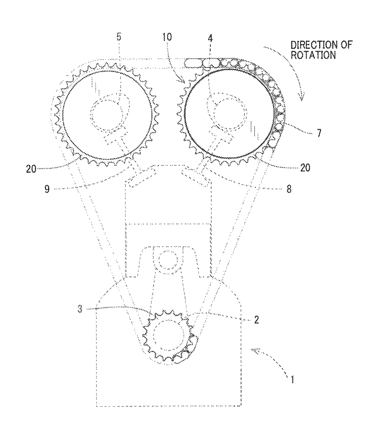
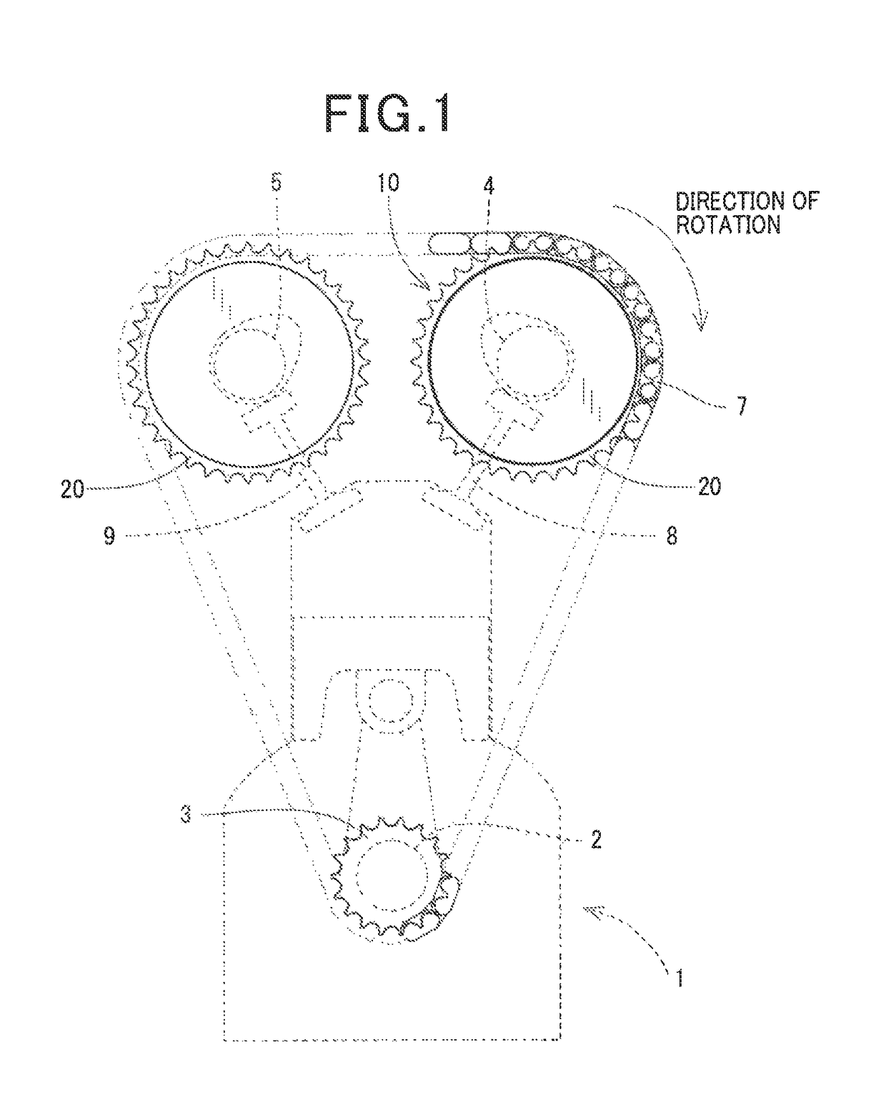
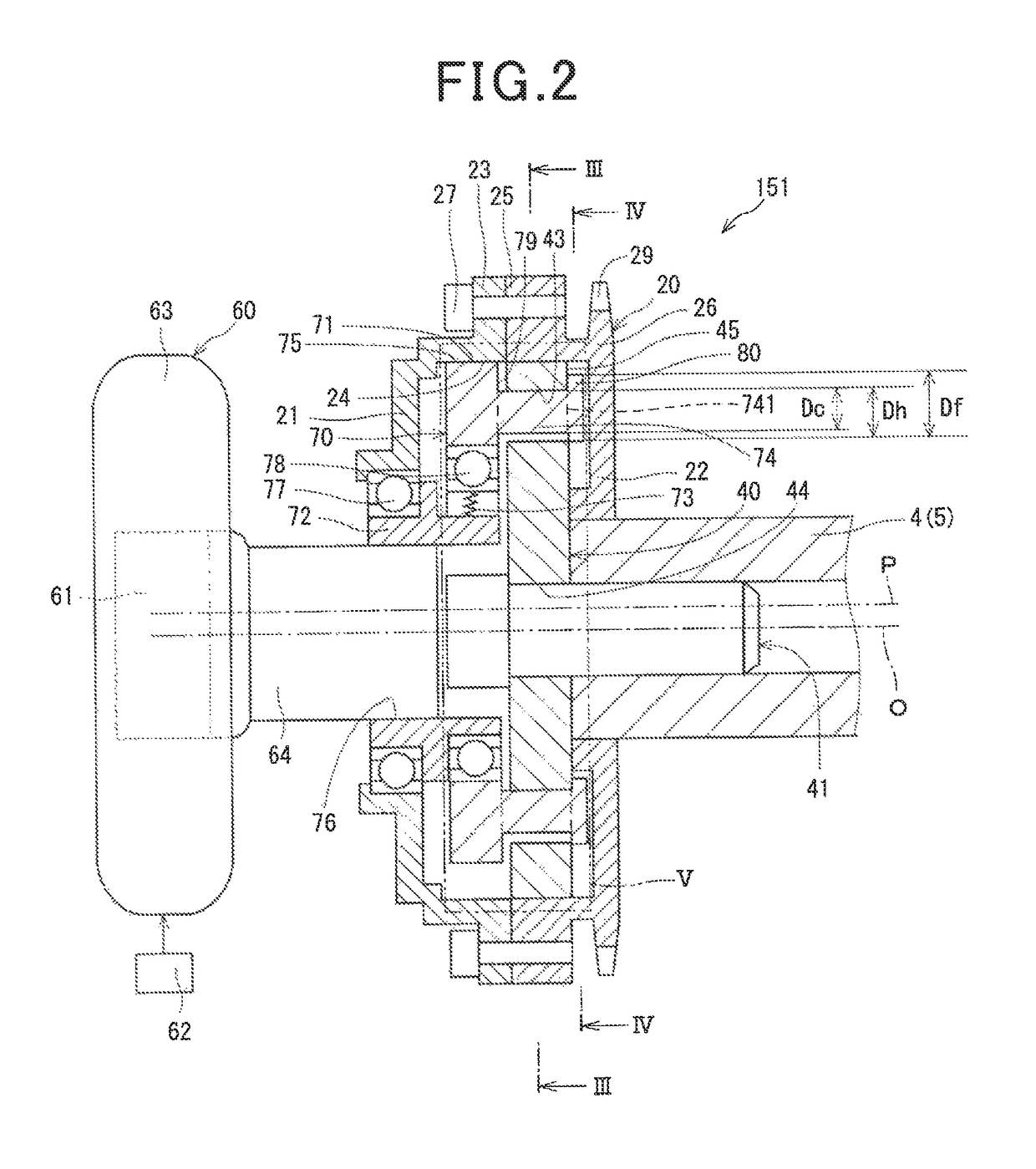
[0065]Each of the cycloidal speed reducer 151 is, as illustrated in FIG. 2, equipped with the first rotor 20, the second rotor 40, the control unit 60, and the third rotor 70.

[0066]The first rotor 20 is of a box shape including the bottomed cylindrical gear member 21 and the bottomed cylindrical sprocket 22 which are arranged coaxially with each other. The first rotor 20 has an inner chamber formed therein and is rotatable.

[0067]The first rotor 20 is mounted coaxially with the camshaft 4 or camshaft 5.

[0068]The gear member 21 is equipped with the protrusion 23 and the first internal gear 24.

[0069]The protrusion 23 is formed on the gear member 21 and extends outwardly from an outer periphery of the gear member 21 in a radial direction of the gear member 21.

[0070]The first internal gear 24 is formed on the inner peripheral wall of the gear member 21. The first internal gear 24 has teeth whose tops face the radial center of the gear member 21. The first internal gear 24, as referred to...

second embodiment

[0108]FIG. 6 illustrates the cycloidal speed reducer 152 according to the second embodiment which has the intermediate member 82 disposed between the second rotor 40 and the flanges 84. The intermediate member 82 is of a plate shape. Other arrangements are identical with those in the first embodiment.

[0109]Specifically, the intermediate member 82 is, as illustrated in FIG. 7, made of an annular disc and has formed therein eight through-holes 83 which are aligned or coincide with the holes 43 and through which the cylindrical pins 74 pass. The through-holes 83 are identical in configuration with the cylindrical pins 74. The term “identical with” or “equal to” means within usual tolerances and errors. FIG. 7 illustrates the intermediate member 82 using dots in order to facilitate visual perception thereof.

[0110]Referring back to FIG. 6, when the flange end surface 81 contacts the intermediate member 82, the flanges 84 work in the same way as in the first embodiment. The use of the int...

third embodiment

[0111]FIGS. 8 and 9 illustrate the cycloidal speed reducer 153 according to the third embodiment which is different in configuration of the cylindrical pins 174 from the first embodiment. Other arrangements are identical, and explanation thereof in detail will be omitted here.

[0112]Specifically, the cycloidal speed reducer 153 is, as illustrated in FIGS. 8 and 9, equipped with the cylindrical pins 174 each of which has the middle portion 742 constricted in the form of a waist. In this embodiment, the diameter of the middle portion 742 is defined as Dm, the diameter of the end 741 of each of the cylindrical pins 174 is defined as De, and the end 743 of each of the cylindrical pins 174 leading to the third rotor end surface 79 is defined as Dn.

[0113]Each of the cylindrical pins 174 is shaped to have the diameters De and Dn equal to each other (De=Dn). Each of the cylindrical pins 174 is also shaped to have the diameter Dm which is smaller than the diameters De and Dn (Dm742 serves to ...


PUM


Abstract

An eccentric speed variator includes a first rotor, a second rotor, a third rotor, a cylindrical pin, and a flange. The second rotor has a hole formed therein. The third rotor rotates eccentrically to change a relative rotation phase between the first and second rotors. The cylindrical pin extends through the hole of the second rotor to establish mechanical engagement between the second and third rotors. The flange is secured to or integrally formed with an end of the cylindrical pin. In operation, when the flange contacts the outside wall of the second rotor, it serves to minimize inclination of the third rotor relative to the second rotor, thereby reducing local friction between the second and third rotors to eliminate undesirable mechanical vibration or noise. This structure also enables parts of the cycloidal speed reducer to be decreased, which leads to a reduced size of the cycloidal speed reducer.

Description

CROSS REFERENCE TO RELATED DOCUMENT[0001]The present application claims the benefit of priority of Japanese Patent Application No. 2016-101154 filed on May 20, 2016, the disclosure of which is incorporated herein by reference.BACKGROUND1 Technical Field[0002]This disclosure relates generally to an eccentric speed variator which may be used with a variable valve timing mechanism for automotive vehicles.2 Background Art[0003]Japanese Patent First Publication No. 2009-257493 discloses a cycloidal speed reducer which has two rotors which are disposed in a rotatable housing and eccentrically rotate 180° out of phase from one another. The use of the two rotors leads to a rise of mechanical vibration or noise. In order to alleviate such a problem, Japanese Patent First Publication No. 2000-120809 teaches use of three rotors in a rotatable housing in a cycloidal speed reducer.[0004]The use of the three rotors, however, results in an increased length or increased number of parts of the cyclo...

Claims


Application Information

Patent Timeline
Patent Type & Authority Patents(United States)
IPC IPC(8): F16H1/32B60K17/04
CPCB60K17/046F16H1/32
Inventor HONDA, YUKIHIROOKADA, HIROSHIKUWAYAMA, AKINORI
Owner DENSO CORP
Why Eureka
Try Eureka