Wind turbine

a technology of wind turbines and friction bearings, applied in the direction of machines/engines, mechanical equipment, roller bearings, etc., can solve the problems of increasing the complexity of assembling and servicing of individual friction bearing segments, and achieve the effect of low complexity

Active Publication Date: 2020-02-06
THYSSENKRUPP ROTHE ERDE GMBH +1
View PDF2 Cites 2 Cited by
  • Summary
  • Abstract
  • Description
  • Claims
  • Application Information

AI Technical Summary

Benefits of technology

[0006]In the case of the bearing assembly according to the invention, a first compression chamber is formed between the first bearing ring and the first friction bearing segment. A pressure in the first compression chamber which pushes the first friction bearing segment in the direction of the first friction face of the second bearing ring and acts as a spring / damper system can be generated by directing a lubricant into the first compression chamber. A second compression chamber in which a lubricant film having a lubricant gap width can be configured is formed between the first friction bearing segment and the second bearing ring, in particular the friction face of the second bearing ring. The first and the second compression chamber are connected by a duct that runs through the first friction bearing segment such that the second compression chamber can be supplied with lubricant by way of the duct. A pressure equalization between the first compression chamber and the second compression chamber can take place by way of the duct. In the case of the bearing assembly according to the invention, it is not necessary for separate springs to be provided for elastically mounting the first friction bearing segments. Less complexity in terms of assembling and servicing results. Furthermore, the damping of undesirable vibrations can be enabled by way of the bearing assembly according to the invention such that improved smooth running can be obtained.
[0015]It is advantageous for a sealing element to be disposed between the friction bearing segment and the first bearing ring, in particular the receptacle pocket, such that any undesirable outflow of lubricant from the first compression chamber, that is to say from the rear side of the friction bearing segment about the latter, can be prevented. It can be achieved on account of the sealing element that an exchange of lubricant can take place substantially, preferably exclusively, by way of the duct of the friction bearing segment.
[0016]According to one advantageous design embodiment it is provided that the first friction bearing segment is configured in such a manner that a plurality of second compression chambers, in particular three or four second compression chambers, are formed between the first friction bearing segment and the second bearing ring, wherein the first compression chamber and the plurality of second compression chambers are connected by way of a plurality of ducts that run through the first friction bearing segment. The friction bearing segment on that side thereof that faces the friction face of the second bearing ring can comprise a plurality of protrusion which form lateral delimitations for a plurality of, in particular three or four, second compression chambers. Any undesirable tilting of the friction bearing segment in relation to the second bearing ring can be minimized on account of the plurality of second compression chambers that are formed between the first friction bearing segment and the second bearing ring. This means that contact with the second bearing ring by a tilted friction bearing segment can be prevented in the event of a malfunction in the pressure supply, for example a loss of pressure.

Problems solved by technology

However, in the case of such bearings which comprise a large number of friction bearing segments of this type, said mechanical or hydraulic springs for mounting the individual friction bearing segments are associated with an increased complexity in terms of assembling and servicing.

Method used


Image

  • Wind turbine
  • Wind turbine
  • Wind turbine

Examples


Embodiment Construction

[0043]In the various figures, the same parts are always provided with the same designations, and are therefore in each case also generally only referred to or mentioned once.

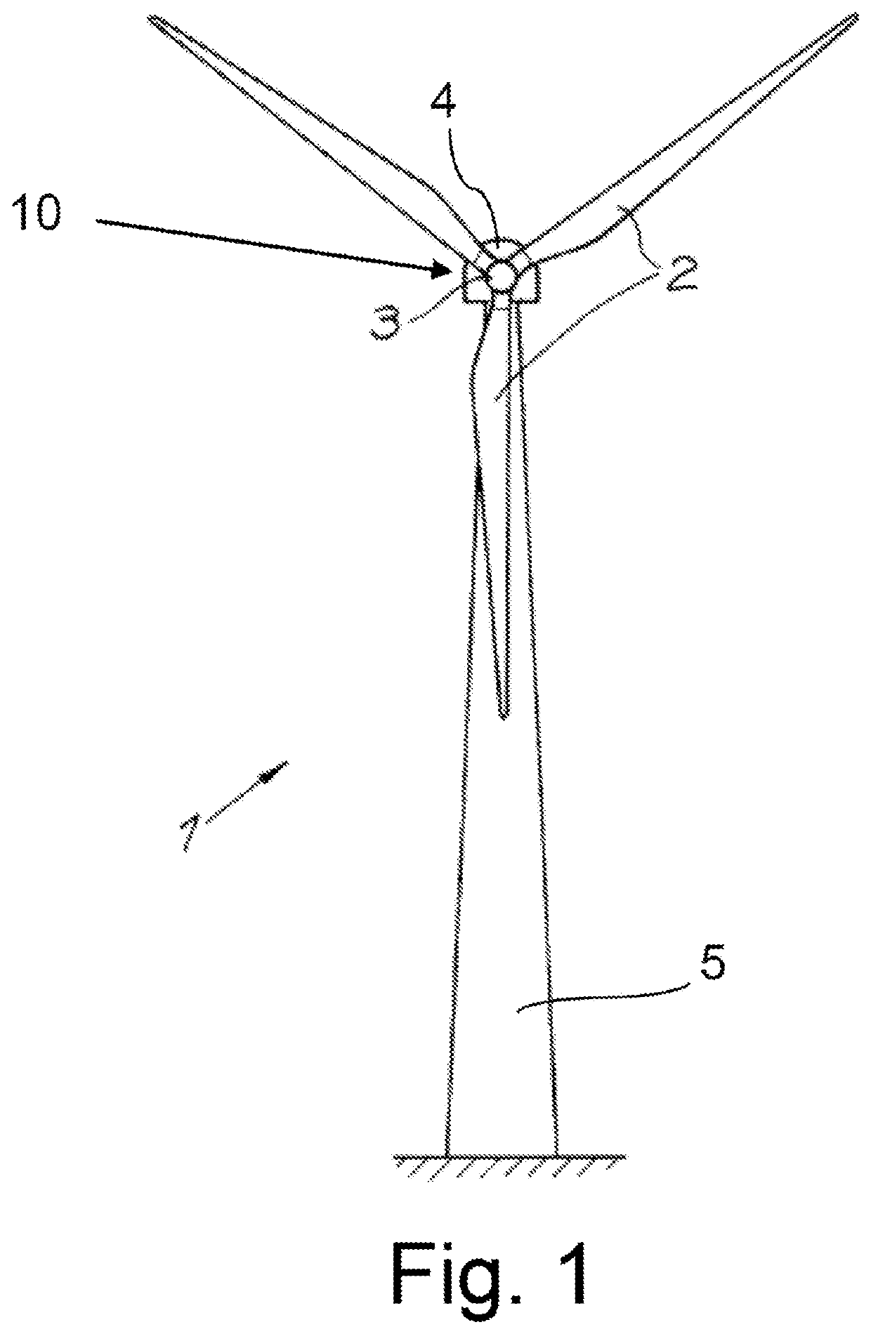
[0044]A wind turbine 1 which comprises a tower 5 and a nacelle 4 that is disposed so as to be rotatable in relation to the tower 5 is shown in FIG. 1. A rotor 3 is rotatably mounted on the nacelle 4 by a rotor shaft. The rotor shaft is mounted by way of a bearing assembly 10 according to the invention. A first bearing ring 11 of the bearing assembly 10 herein is configured as a stationary bearing ring. A second bearing ring 12 which is rotatable in relation to the first bearing ring 10 is connected in a rotationally fixed manner to the rotor shaft. A plurality of rotor blades 2 are provided on the rotor 3.

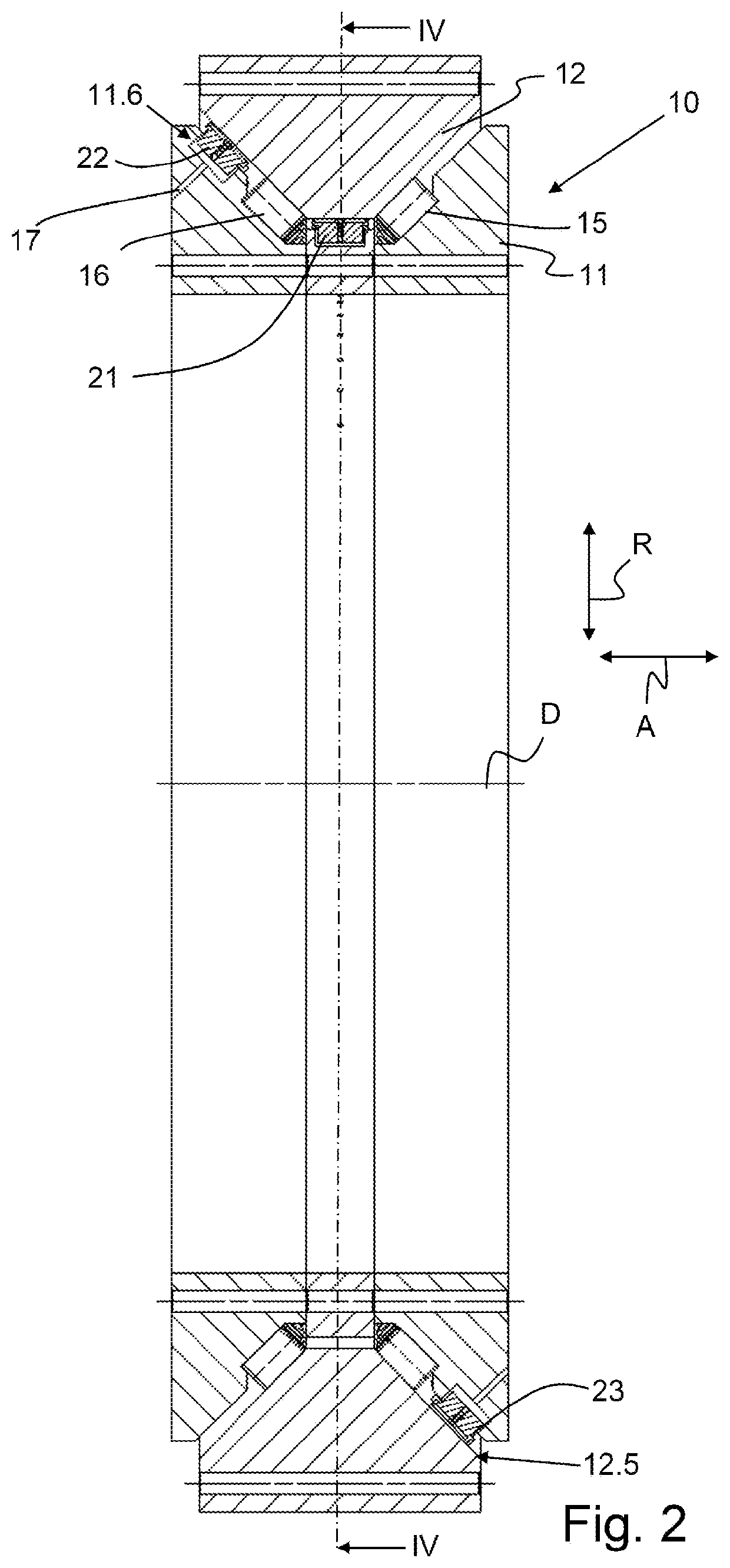
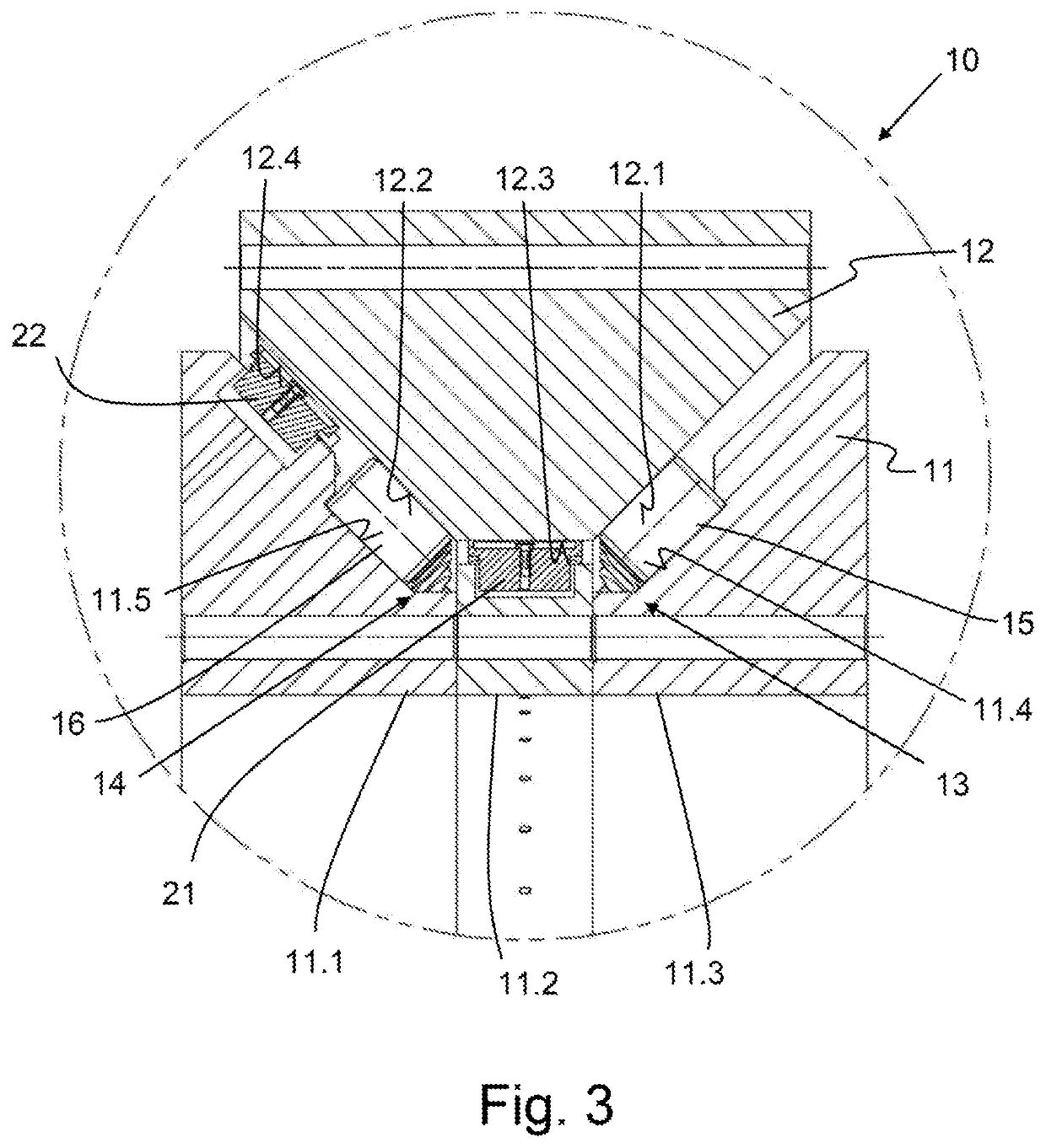
[0045]The bearing assembly 10 is configured as a large roller bearing having a diameter in the range from 1 m to 10 m, preferably from 3 m to 7 m, particularly preferably from 4 m to 6 m, for example 2.5 m. Var...


PUM

PropertyMeasurementUnit
diameteraaaaaaaaaa
diameteraaaaaaaaaa
diameteraaaaaaaaaa

Abstract

A wind turbine includes a rotor shaft. The rotor shaft is mounted via a bearing assembly having a first bearing ring and a second bearing ring mounted to rotate in relation to the first bearing ring. A hydrostatically supported first friction bearing segment is disposed on the first bearing ring and interacts with a first friction face that is disposed on the second bearing ring. The first friction bearing segment is received in a receptacle pocket of the first bearing ring such that a first compression chamber is formed between the first bearing ring and the first friction bearing segment. The first friction bearing segment is configured such that a second compression chamber is formed between the first friction bearing segment and the second bearing ring, wherein the first compression chamber and the second compression chamber are connected by a duct that runs through the first friction bearing segment.

Description

PRIOR ART[0001]The present invention relates to a bearing assembly having a first bearing ring and a second bearing ring that is mounted so as to be rotatable in relation to the first bearing ring, wherein at least one hydrostatically supported first friction bearing segment which interacts with a first friction face that is disposed on the second bearing ring is disposed on the first bearing ring.[0002]The bearing assembly according to the invention can be used for mounting a rotor shaft of a wind turbine.[0003]A bearing assembly for mounting such a rotor shaft of a wind turbine is known from DE 10 2011 008 267 A1, said bearing assembly comprising a plurality of hydrostatically supported friction bearing segments. The friction bearing segments are elastically mounted in a spherically configured circumferential face of the outer ring of said bearing assembly. To this end, the friction bearing segments are not fixedly assembled but are disposed on a mechanical or hydraulic spring so ...

Claims


Application Information

Patent Timeline
Patent Type & Authority Applications(United States)
IPC IPC(8): F16C32/06F16C19/38F16C19/50F16C21/00F03D80/70
CPCF03D80/70F16C19/385F16C19/50F16C32/0696F16C2360/31F16C2380/00F16C21/00F16C32/0651F16C2322/39F16C32/0666Y02E10/72F16C2300/14F16C32/0633
Inventor LÜNEBURG, BERNDROLLMANN, JÖRGELFERT, GUNTHER
Owner THYSSENKRUPP ROTHE ERDE GMBH
Why Eureka
Try Eureka