
Vehicle rigid axle and method of manufacturing same

a technology of rigid axle and axle, which is applied in the direction of wheel manufacturing, wheel transportation and packaging, and wheels

Active Publication Date: 2022-02-22
EBERT CONSULTING GMBH
View PDF13 Cites 0 Cited by
  • Summary
  • Abstract
  • Description
  • Claims
  • Application Information

AI Technical Summary

Benefits of technology

The invention is a vehicle rigid axle that can be made with fewer components than previous versions. The design of the hollow body reduces the risk of weakening and allows for the spring bracket to be placed inside. This prevents bending moments from being introduced and increases the load carrying capacity. The plunger is made of two segments, which saves material and simplifies manufacture. The patent text describes the advantages and features of the invention.

Problems solved by technology

The formation of the hollow body from two shell elements, preferably formed by forming, also reduces the number of weld seams and thus causes mechanical weakening of the rigid axle.

Method used


Image

  • Vehicle rigid axle and method of manufacturing same
  • Vehicle rigid axle and method of manufacturing same
  • Vehicle rigid axle and method of manufacturing same

Examples


Embodiment Construction

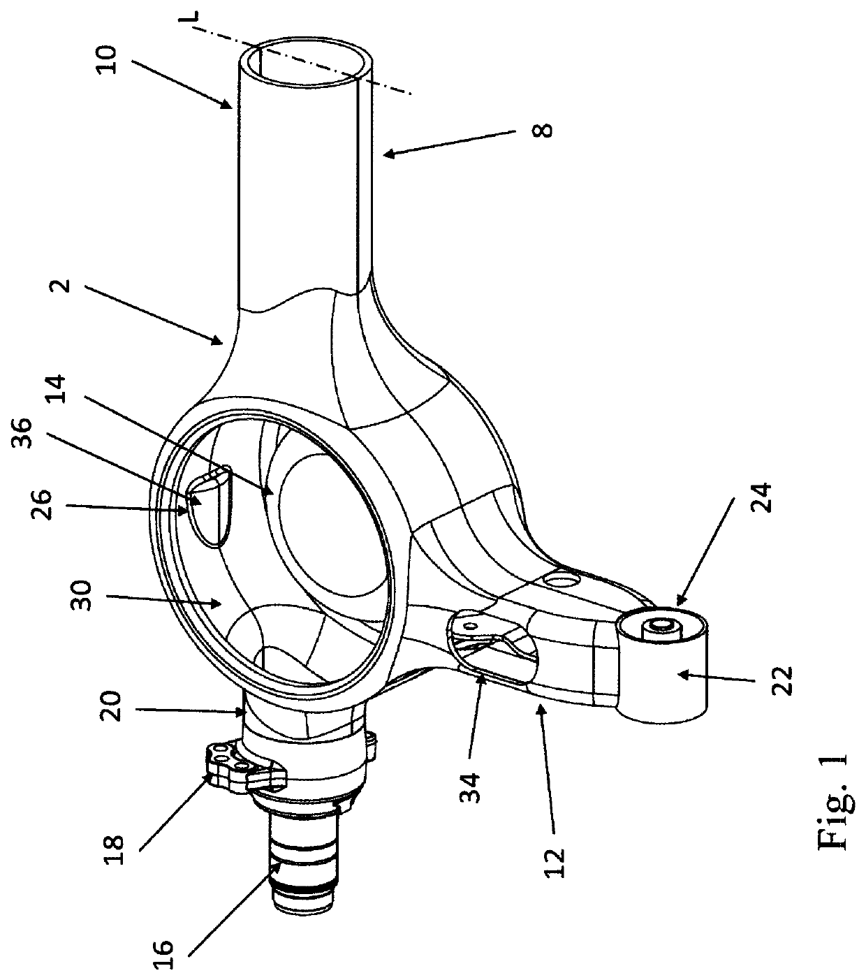
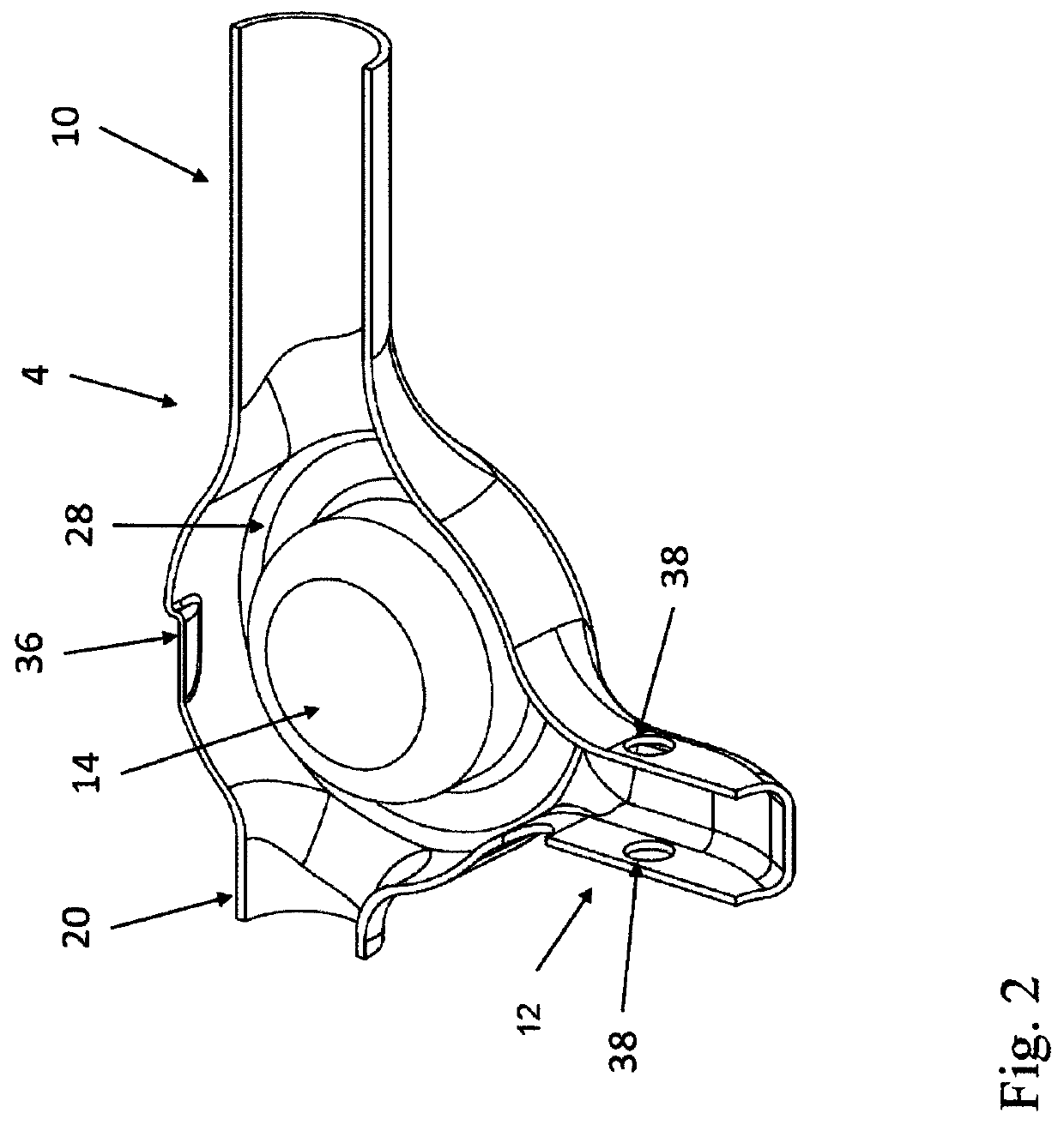
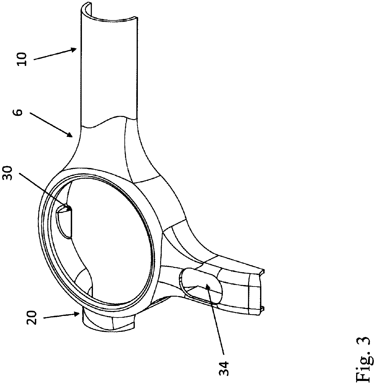
[0025]The Figures show an axle beam marked with reference numeral 2, formed by joining a lower shell element 4 and an upper shell element 6. The two shell elements 4, 6 are joined together by welding to form the axle beam 2. The connecting line usually extends in the neutral fiber of a bending load on the axle beam 2.

[0026]The two shell elements 4, 6 together form an axle beam section 10, a trailing arm 12 and a spring bracket 14. FIG. 1 shows only half of the complete vehicle rigid axle 8. The distal end of the axle beam section 10 lies on the central longitudinal axis of the vehicle, regularly of a truck trailer. Thus, on the other side of the longitudinal axis marked L, the structure shown to the left of it in FIG. 1 is repeated.

[0027]On the side opposite the spring bracket 14 in relation to the axle beam section 10, an axle journal 16 is welded on, which is fitted with a conventionally shaped brake mounting flange 18. The axle journal 16 is connected by friction welding to an ax...


PUM

PropertyMeasurementUnit
thicknessaaaaaaaaaa
thicknessaaaaaaaaaa
thicknessaaaaaaaaaa

Abstract

A vehicle rigid axle with an axle beam, at the ends of which axle journals or wheel carriers, are arranged, and trailing arms rigidly attached with a spring bracket for supporting an air-suspension bellow, and a method for manufacturing the vehicle rigid axle. An axle beam section extending between the trailing arms, a trailing arm adjoining the axle beam section and the spring bracket are formed by two shell elements connected to each other, which form a hollow body. In an embodiment, the spring bracket is formed by a lower shell element forming an axle beam section extending between the two trailing arms, and the spring bracket is arranged so that the air-suspension bellow mounted on the spring bracket is penetrated by the central longitudinal axis of the axle beam section. Two shell elements made of sheet metal are formed and joined together to form a hollow body.

Description

FIELD OF THE INVENTION[0001]The present invention refers to a vehicle rigid axle with an axle beam and trailing arms. Such a vehicle rigid axle is known from DE 101 40 856 B4 and DE 102 31 337 B3 respectively.BACKGROUND OF THE INVENTION[0002]In the case of the aforementioned vehicle rigid axle, a tubular axle beam extending transversely to the direction of the vehicle is welded to an axle guide formed by a shell-shaped hollow body which is welded at one end to a bearing sleeve and at its other end forms annular connecting surfaces for connecting the axle beam on the one hand and an axle journal on the other hand, which are each connected by welding to the hollow body forming the axle guide. This axle guide also has connecting surfaces for a spring bracket. The spring bracket consists of an upper and a lower sheet-metal belt and a web provided between them and fixed by welding with the belts. This spring bracket is welded to the axle guide. The spring bracket essentially extends in e...

Claims


Application Information

Patent Timeline
Patent Type & Authority Patents(United States)
IPC IPC(8): B60B35/00B60G9/00B60G11/28
CPCB60B35/007B60G9/003B60G11/28B60B2310/302B60B2360/141B60G2200/31B60G2202/152B60G2204/126B60G2204/148B60G2204/4306B60G2206/30B60G2206/424B60G11/27B23P15/00B60G2206/811B60G2206/80B23P2700/50B60B35/04B60B35/08B60G9/006
Inventor EBERT, JORG
Owner EBERT CONSULTING GMBH
Learn More