Ultrafine equipment oscillation mechanism

A technology of oscillating mechanism and equipment, applied in the directions of ultra-finishing machines, metal processing equipment, manufacturing tools, etc., can solve problems such as limitations, and achieve the effects of stable amplitude and vibration frequency, ensuring coaxiality, and adjustable amplitude and vibration frequency.

Inactive Publication Date: 2019-12-27
ZHEJIANG 81 PRECISION MACHINERY CO LTD
View PDF1 Cites 0 Cited by
  • Summary
  • Abstract
  • Description
  • Claims
  • Application Information

AI Technical Summary

Problems solved by technology

[0007] In view of the above problems, the present invention provides an oscillation mechanism of ultra-precision equipment, which drives the rotating shaft to drive the amplitude adjustment assembly to rotate synchronously by means of a rotary drive device, and directly cooperates intermittently with the protrusion on the longitudinal pin of the oscillator. There is no matching clearance, which solves the limitation of the machining accuracy of the super-finishing machine due to the matching clearance, and improves the machining accuracy of the super-finishing machine

Method used


Image

  • Ultrafine equipment oscillation mechanism
  • Ultrafine equipment oscillation mechanism
  • Ultrafine equipment oscillation mechanism

Examples


Embodiment 1

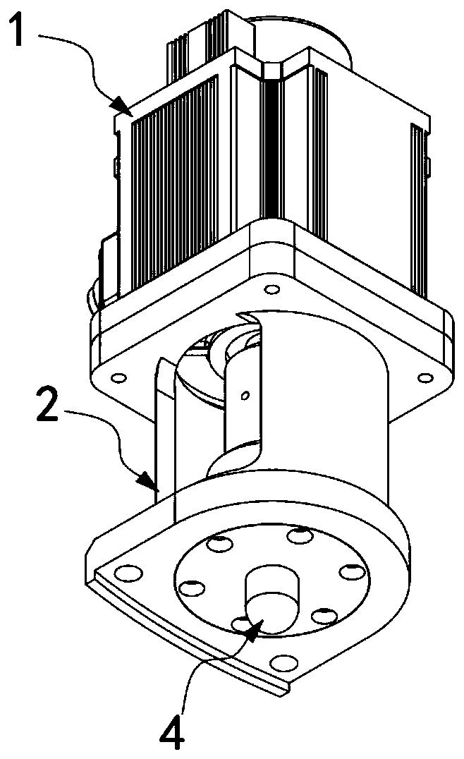
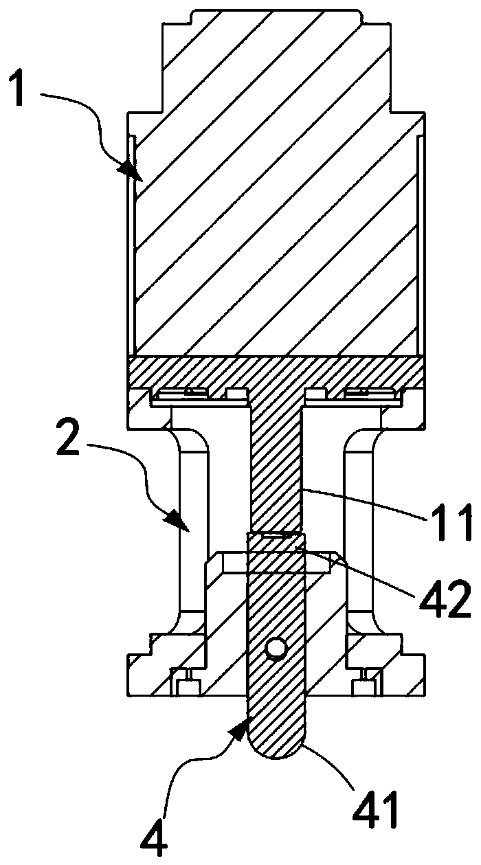
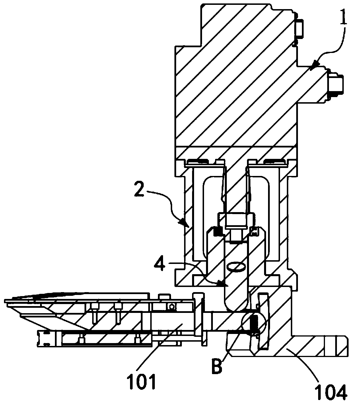
[0045] like Figures 1 to 6 As shown, an oscillation mechanism for ultra-precision equipment includes a vertically arranged rotary drive device 1 and an oscillator seat 2 coaxially sleeved outside the rotary shaft 11 of the rotary drive device 1, and also includes:

[0046] An amplitude adjustment assembly 3, the amplitude adjustment assembly 3 is installed below the rotating shaft 11, and it rotates synchronously with the rotating shaft 11; and

[0047]The oscillator longitudinal pin 4, the oscillator longitudinal pin 4 is coaxially installed inside the oscillator seat 2, and is located below the amplitude adjustment assembly 3, the oscillator longitudinal pin 4 includes The working end 41 and the matching end 42 of the end, the working end 41 is always in conflict with the object to be oscillated, and the matching end 42 is protruded along its circumferential direction to intermittently interfere with the amplitude adjustment assembly 3 raised portion a421;

[0048] The ro...

Embodiment 2

[0055] Figure 7 It is a schematic structural view of Embodiment 2 of an ultra-precision equipment oscillation mechanism of the present invention; as Figure 7 As shown, the components that are the same as or corresponding to those in Embodiment 1 use the corresponding reference numerals as in Embodiment 1. For the sake of simplicity, only the differences from Embodiment 1 will be described below. The Example 2 with figure 1 Example 1 shown differs in that:

[0056] like Figure 7 As shown, an oscillation mechanism of ultra-precision equipment, the control part 31 is a ball installed on the lower end of the rotating shaft 11 .

[0057] It should be noted that, different from Embodiment 1, the control part 31 in this embodiment is a ball structure, which directly rolls and is placed in the groove at the lower end of the rotating shaft 11 .

[0058] It should be noted that, compared with the control part 31 provided with bumps, the control part 31 with the ball structure has...

Embodiment 3

[0060] Figure 8 It is a structural schematic diagram of Embodiment 3 of an ultra-precision equipment oscillation mechanism of the present invention; as Figure 8 As shown, the components that are the same as or corresponding to those in Embodiment 2 use the corresponding reference numerals as in Embodiment 2. For the sake of simplicity, only the differences from Embodiment 2 will be described below.

[0061] like Figure 8 and Figure 9 As shown, an oscillating mechanism for ultra-precision equipment also includes an elastic connector 5 coaxially sleeved outside the rotating shaft 11, and sequentially includes transition connections along its axial direction from top to bottom. The claw part 51 and the threaded part 52, the claw part 51 includes a plurality of claws 511 equidistantly arranged along the axial circumference, and there is an adjustment gap 512 between two adjacent claws 511, and the The diameter of the end portion of the claw portion 51 away from the threaded...


PUM


Abstract

The invention provides an ultrafine equipment oscillation mechanism comprising a rotary driving device and an oscillator seat arranged outside a rotary shaft of the rotary driving device coaxially ina sleeving mode. The ultrafine equipment oscillation mechanism further comprises an amplitude adjusting assembly and an oscillator longitudinal pin. The rotary driving device is utilized for driving the rotary shaft amplitude adjusting assembly to rotate synchronously, the oscillator longitudinal pin oscillates in a reciprocating fixed-amplitude mode in the vertical direction in the oscillator seat through intermittent contact of the amplitude adjusting assembly and the matching end of the oscillator longitudinal pin, and adjustable amplitude and oscillation frequency of the oscillation mechanism are achieved by adjusting the contact distance of an amplitude assembly and the matching end and the quantity of convex parts while the technical problem of insufficient stability of the oscillation mechanism is solved.

Description

technical field [0001] The invention relates to the technical field of oscillating mechanical structures on superfinishing equipment, in particular to an oscillating mechanism for superfinishing equipment. Background technique [0002] At present, the oilstone oscillation method commonly used in superfinishing machines is to convert the rotation of ordinary AC motors into reciprocating oscillations of swing mechanisms through space mechanisms. Although the oscillation frequency can be changed by changing the speed of ordinary AC motors, this structure borrows Regarding the output of the conversion mechanism, due to the relationship between the inertia and the transmission path, there is a large deviation between the actual output oscillation frequency and oscillation amplitude and the preset oscillation frequency and oscillation amplitude. Machining accuracy needs further improvement. [0003] For example, in the patent document with the patent number CN201110296398.4 (here...

Claims


Application Information

Patent Timeline
Patent Type & Authority Applications(China)
IPC IPC(8): B24B35/00
CPCB24B35/00
Inventor 陈仁波孙振国刘绿林周华王兵谢志强王德东
Owner ZHEJIANG 81 PRECISION MACHINERY CO LTD
Why Eureka
Try Eureka