Backlight apparatus, control method for controlling the same, and image display apparatus

a control method and backlight technology, applied in the direction of instruments, light sources, electroluminescent light sources, etc., can solve the problems of deterioration correction, long time period, and several minutes, and achieve the effect of accurate measurement and suppression of uneven luminan

Inactive Publication Date: 2012-08-09
CANON KK
View PDF7 Cites 18 Cited by
  • Summary
  • Abstract
  • Description
  • Claims
  • Application Information

AI Technical Summary

Benefits of technology

[0007]When the luminance control is performed for each of the LED blocks in accordance with the local dimming control, a problem arises in relation to the uneven luminance caused by the dispersion of the secular change for each of the LED blocks. When the LED blocks are successively turned ON (subjected to the lighting) in a time sharing manner, and the luminance is detected by using an optical sensor (photo sensor), then the luminance of each of the LED blocks can be accurately measured without being affected by the light coming from the other LED blocks. Further, it is considered that the luminance dispersion can be corrected for each of the LED blocks and the uneven luminance can be suppressed by correcting the luminance of LED for each of the LED blocks on the basis of the measurement result. The process, in which the fluctuation of the luminance caused by the secular change of LED in relation to each of the LED blocks is corrected as described above, is herein referred to as “LED deterioration correcting process”.

Problems solved by technology

When the luminance control is performed for each of the LED blocks in accordance with the local dimming control, a problem arises in relation to the uneven luminance caused by the dispersion of the secular change for each of the LED blocks.
If the LED deterioration correcting process is executed one by one for all of the hundreds of LED blocks, a long period of time (for example, about several minutes) is required until the LED deterioration correcting process is completed for all of the LED blocks.
A long period of time is required until the LED deterioration correcting process is completed for all of the LED blocks.
Therefore, there is such a possibility that the temperature of the backlight apparatus may be fluctuated (lowered) during the period in which the LED deterioration correcting process is executed.
If such a situation arises, there is such a possibility that the uneven luminance cannot be suppressed sufficiently, even when the LED deterioration correcting process is performed for all of the LED blocks.

Method used


Image

  • Backlight apparatus, control method for controlling the same, and image display apparatus
  • Backlight apparatus, control method for controlling the same, and image display apparatus
  • Backlight apparatus, control method for controlling the same, and image display apparatus

Examples


first embodiment

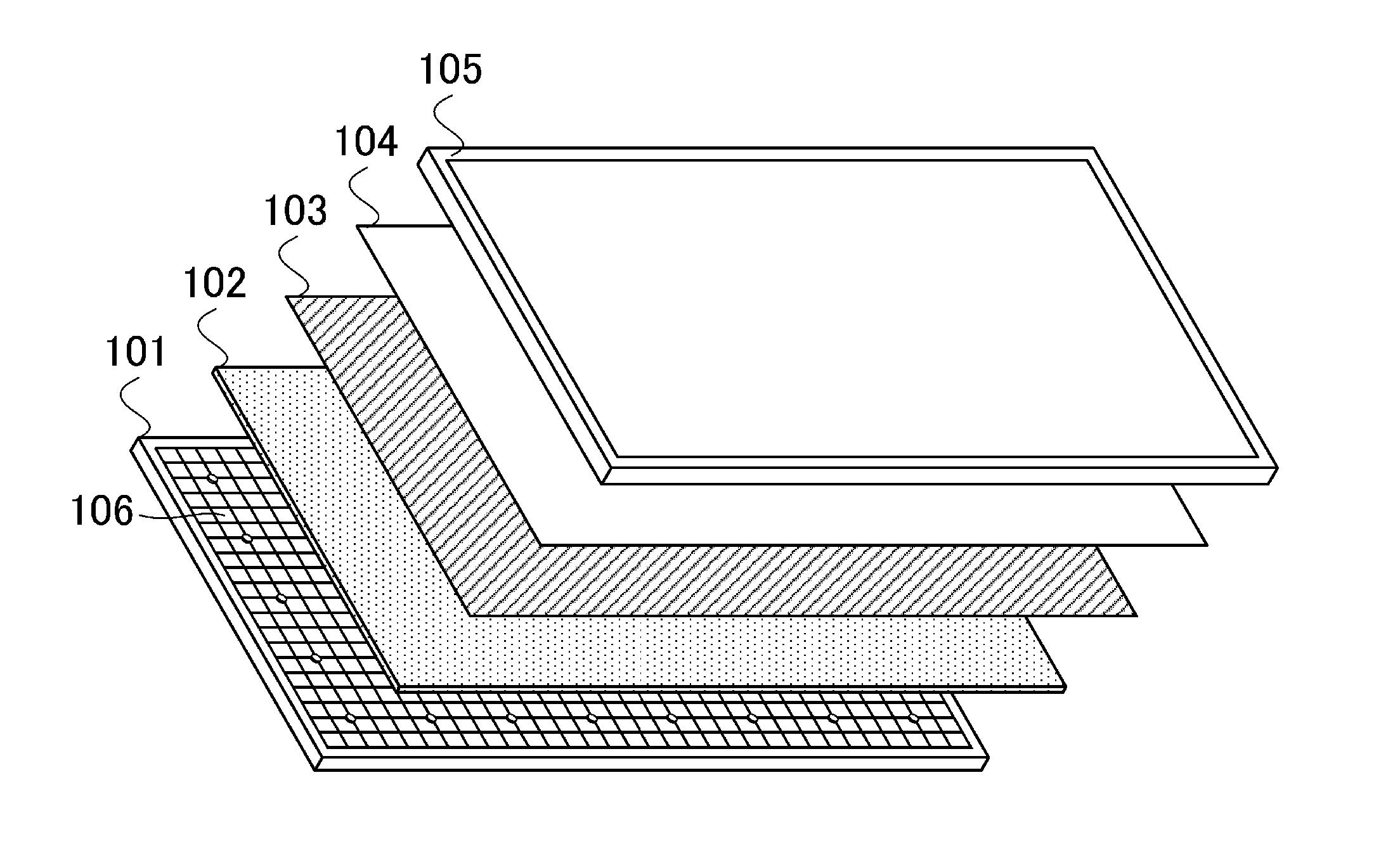
[0034]FIG. 1 shows constitutive parts of an image display apparatus to which the present invention is applicable. A direct(-underneath) type LED backlight module 101 is used as a backlight for radiating the white light onto a back surface of a color liquid crystal panel 105. The direct type LED backlight module 101 is divided into 640 LED blocks 106 (light source blocks) in total in which 20 LED blocks 106 are provided in the vertical direction and 32 LED blocks 106 are provided in the lateral direction. The luminance can be controlled independently from each other for each of the LED blocks (in the unit of light source block).

[0035]The larger the number of divided LED blocks 106 is, the more improved the accuracy of division of the display area in the local dimming control is. One LED block is an assembly of one LED (light source) or a plurality of LED's (light sources) for performing the light emission for one of the plurality of divided areas obtained by dividing the light emitti...

second embodiment

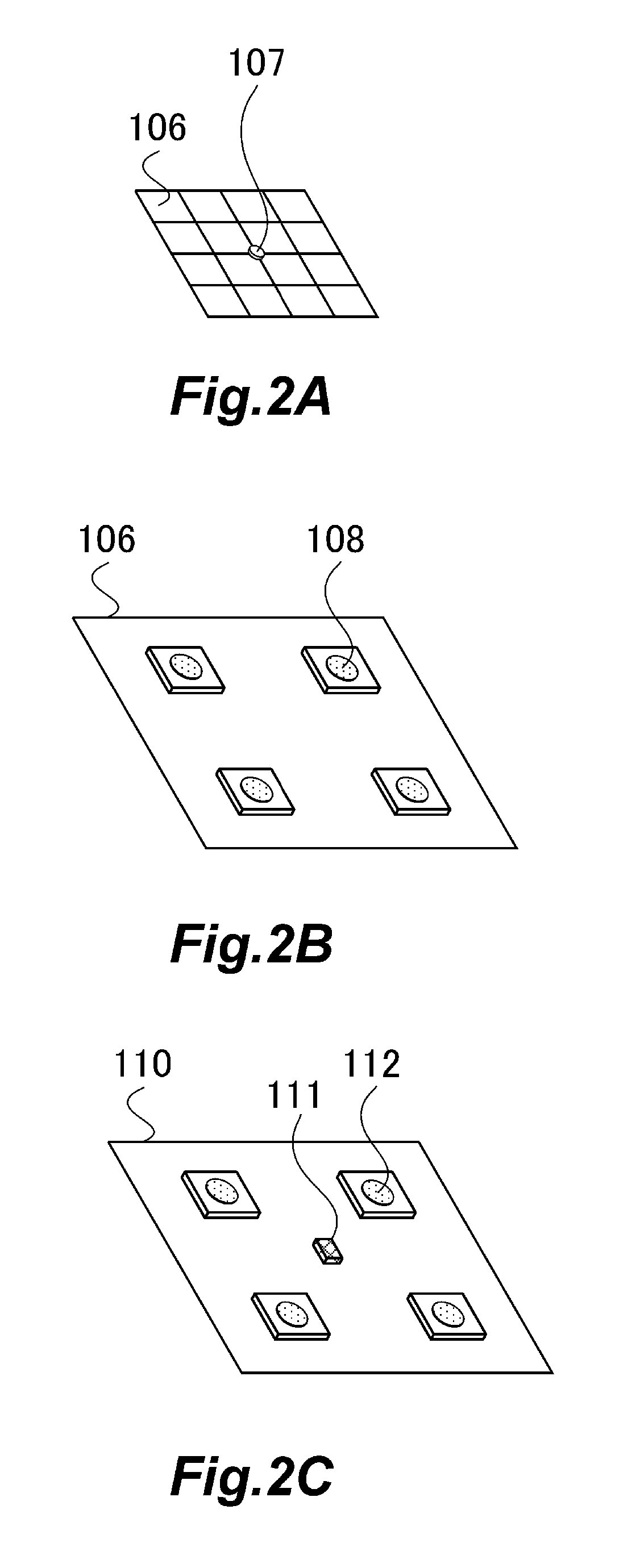
[0077]In the first embodiment, the explanation has been made about the exemplary case in which all of the LED blocks 202 are turned ON at the same time in the LED temperature fluctuation suppressing process to be inserted into the LED deterioration correcting process period. In the second embodiment, an explanation will be made about an exemplary case in which the lighting of any unnecessary LED block is suppressed in the LED temperature fluctuation suppressing process in order to reduce the electric power consumption in the LED temperature fluctuation suppressing process.

[0078]A description will be made below about an exemplary sequence of the LED blocks 106 subjected to the LED deterioration correcting process and exemplary LED block or blocks 106 unnecessary to be turned ON in the LED temperature fluctuation suppressing process executed after the LED deterioration correcting process for each of the LED blocks 106. It is noted that the points or features are the same as those of t...

third embodiment

[0090]In the first embodiment, the explanation has been made for the exemplary case in which the LED temperature fluctuation suppressing process is executed every time when the LED deterioration correcting process is performed for one of the LED blocks or a plurality of the LED blocks. In other words, the LED temperature fluctuation suppressing process is inserted every time when the LED deterioration correcting process is performed for a predetermined number of LED block or blocks.

[0091]On the other hand, in this embodiment, it is judged whether or not the LED temperature is lowered by not less than a threshold value from the LED temperature provided when the LED deterioration correcting process is started, every time when the LED deterioration correcting process is performed for one of the LED blocks or a plurality of the LED blocks. It is judged whether or not the execution of the LED temperature fluctuation suppressing process is required depending on the judgment result. In oth...


PUM

PropertyMeasurementUnit
luminanceaaaaaaaaaa
temperatureaaaaaaaaaa
temperature fluctuationaaaaaaaaaa

Abstract

A backlight apparatus comprises a light emission control unit which controls light emission of each of a plurality of light source blocks; a luminance detecting unit which detects a luminance of the light source block; and a correcting unit which successively executes a correcting process for the plurality of light source blocks by allowing one light source block to emit light so that a light emission amount of the concerning light source block is corrected on the basis of a detected luminance value and a target value thereof; wherein a temperature fluctuation suppressing process is executed when the correcting unit executes the correcting process, so that a plurality of the light source blocks, which include the light source block assumed to emit light in the correcting process to be executed next time, are simultaneously allowed to emit light for a predetermined period at a predetermined luminance.

Description

BACKGROUND OF THE INVENTION[0001]1. Field of the Invention[0002]The present invention relates to a backlight apparatus, a control method for controlling the same, and an image display apparatus.[0003]2. Description of the Related Art[0004]An image display apparatus is generally constructed such that a backlight apparatus, which emits or radiates the white light, is combined on a back surface of a color liquid crystal panel which has a color filter. As for the light source of the backlight apparatus, a fluorescent lamp such as a cold cathode fluorescent lamp (CCFL) or the like has been in the mainstream. In recent years, an LED backlight apparatus, which uses, as a light source, a light emitting diode (LED) that is superior in view of the electric power consumption, the service life, the color reproducibility, and the environmental load, is also progressively used.[0005]Japanese Patent Application Laid-open No. 2001-142409 describes an image display apparatus wherein an area of an LE...

Claims


Application Information

Patent Timeline
Patent Type & Authority Applications(United States)
IPC IPC(8): G02F1/1335H05B37/02
CPCG09G3/3426G09G2320/0233G09G2320/041H05B33/089H05B33/086H05B33/0866G09G2360/145H05B45/24H05B45/56H05B45/22
Inventor KURITA, MASANAO
Owner CANON KK
Why Eureka
Try Eureka