
Rollable Compact Transparent Splint

Inactive Publication Date: 2012-08-09
WAISMED
View PDF9 Cites 4 Cited by
  • Summary
  • Abstract
  • Description
  • Claims
  • Application Information

AI Technical Summary

Benefits of technology

[0016]It is still another object of the invention to provide a splint which can be directly applied to the skin with no danger of sticking, and which can be easily cleane

Problems solved by technology

Fractured injuries have to be treated with care, as mobility of a fractured bone is very painful, can increase the damage, and can extend the recovery period.
Therefore, they occupy a relatively large space, even when they are not in use.b. Some of them are relatively cumbersome and heavy: Prior art splints are relatively bulky and heavy, therefore they are inconvenient to the medical personnel and the patient.c. They are opaque: When a prior art splint is applied, a visual inspection of the injured extremity requires removal of the splint, as the location of injury cannot be inspected via the opaque splint.d.
They do not provide aeration to the injured extremity: Typically, prior art splints comprise a continuous surface, therefore they do not provide aeration to the injured extremity.e.
Each splint has its own shape and length: Each one-piece splint of the prior art has its own shape, and typically cannot be applied to different extremities, namely, a splint for the hand is not adequate to the leg, etc.f.
Some of them are relatively expensive: Therefore, they are typically designed for multiple uses, and are not disposable.
Moreover, the Sam splint does not provide a manner by which an L-shape fixation can be provided.

Method used


Image

  • Rollable Compact Transparent Splint
  • Rollable Compact Transparent Splint
  • Rollable Compact Transparent Splint

Examples


Embodiment Construction

[0041]The splint of the present invention can assume three states: (a) a packed-state in which the splint assumes a rolled configuration; (b) a pre-use state in which the splint is unrolled, automatically assuming a C-configuration; and (c) a use-state where the splint is applied to the extremity in a C-configuration in cross section, or when a higher rigidity is desired, in a U configuration.

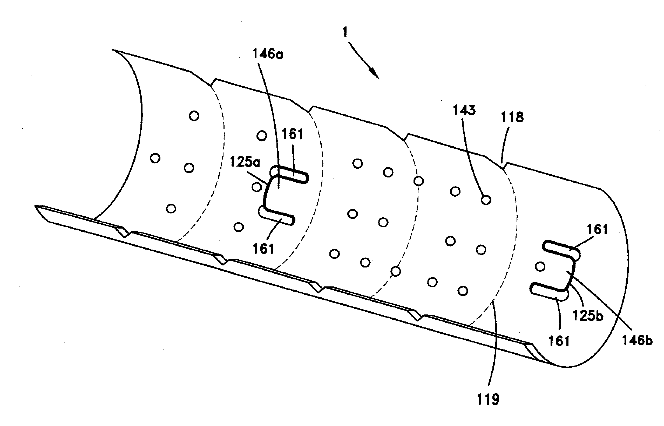
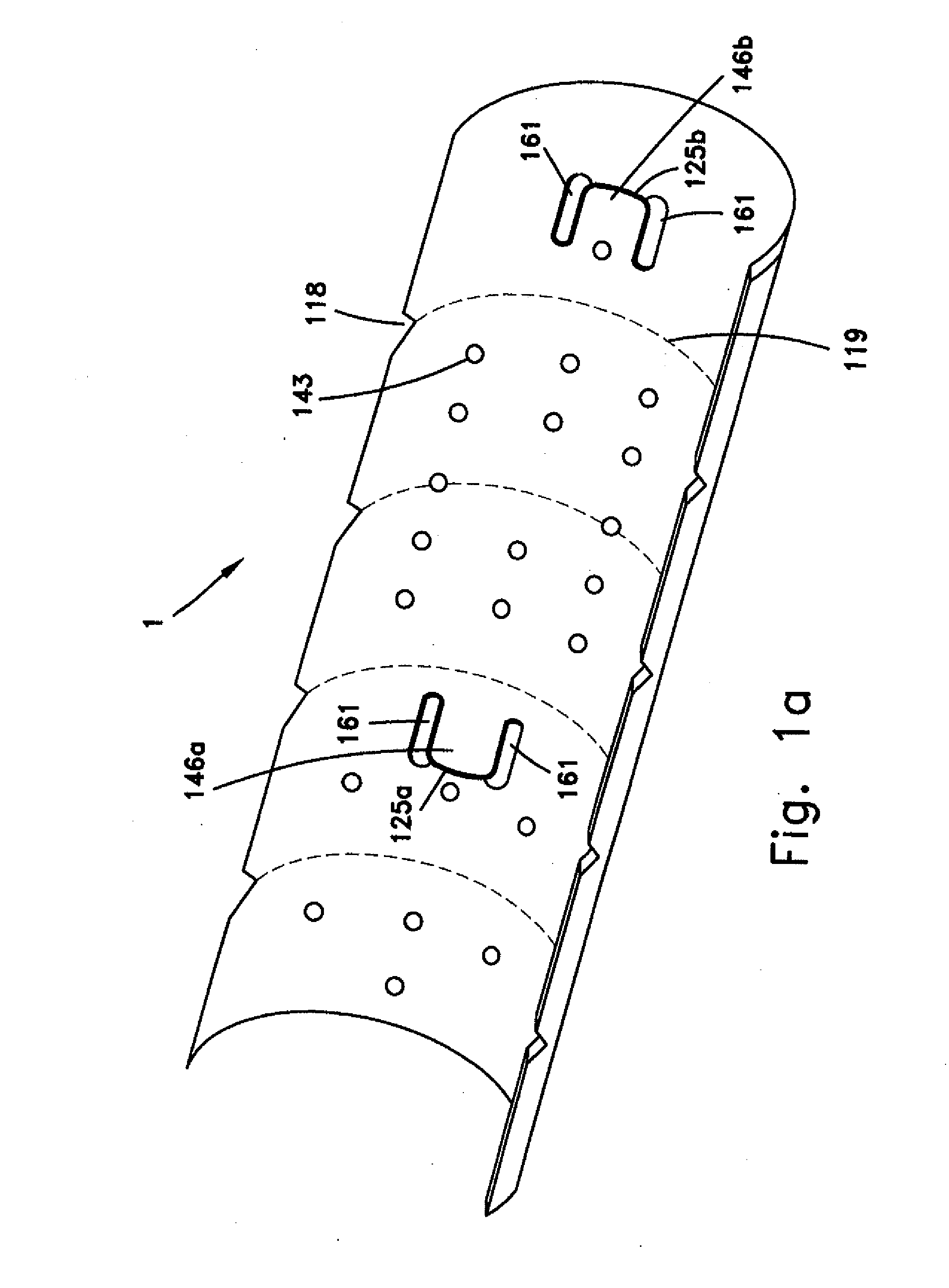
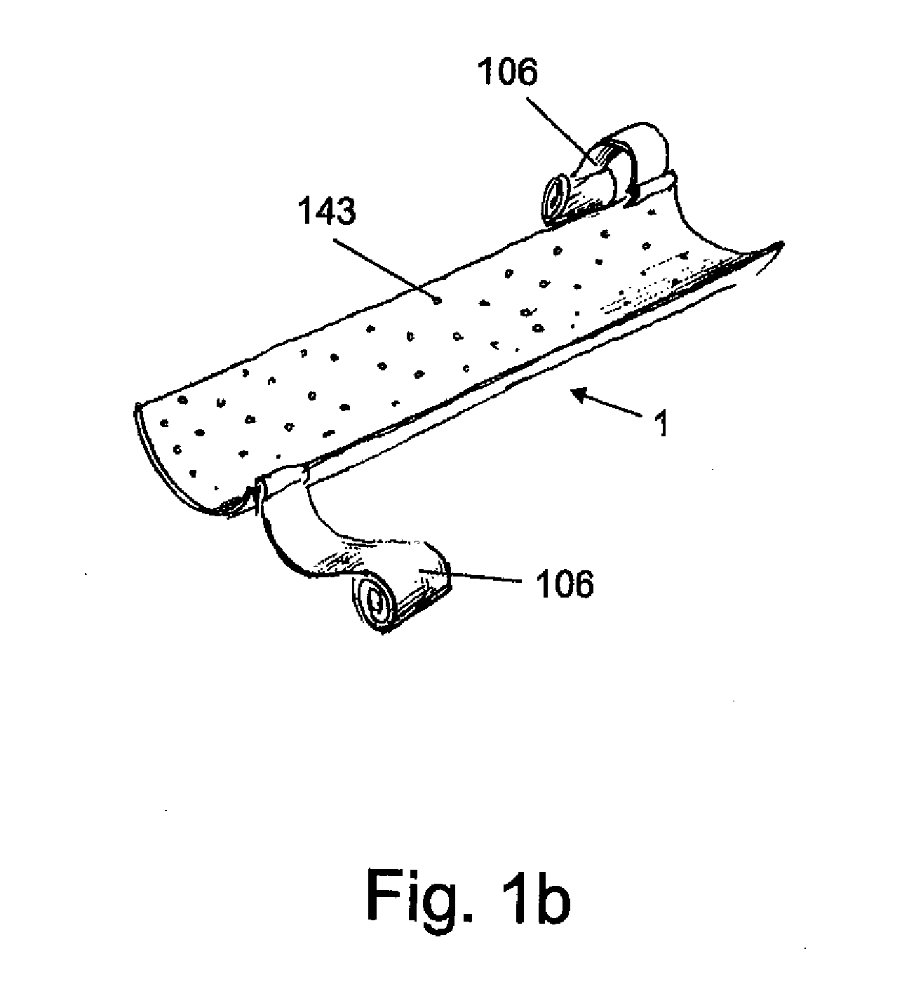
[0042]FIG. 1a shows the fixation splint 1 of the present invention in its pre-use state, according to a first embodiment of the present invention. FIG. 1b shows another embodiment of the splint of the invention, which is provided with built in straps for affixing the splint to the extremity. The splint is essentially rectangular and relatively thin sheet of material, having slightly concave cross-section in its pre-use state. The “slightly concave” cross section of the splint in its pre-use state will be referred to herein as “C-configuration”. As will be further demonstrated hereinafter, the r...


PUM


Abstract

The invention relates to a rollable splint set which comprises an essentially rectangular substrate, said substrate is made of a transparent or translucent thin layer of thermoplastic material having transverse and longitudinal flexibilities that enable the substrate to assume the following three states: (a) a packed-state in which the splint is maintained in a compact rolled configuration; (b) a pre-use, unrolled state in which the splint automatically assumes a C-configuration in cross section; and (c) a use-state in which the splint wraps an extremity in a C-configuration or a U-configuration in cross section.

Description

FIELD OF THE INVENTION[0001]The invention relates in general to the field of medical devices. More particularly, the invention relates to a light-weight fixation splint, which is rollable to assume a compact size when packed, and is transparent for enabling visual inspection of the location of injury during use.BACKGROUND OF THE INVENTION[0002]Fractures of extremities, such as arms, legs, or fingers are very common. The recovery period of a fractured extremity is relatively long, lasting from several weeks to several months. Fractured injuries have to be treated with care, as mobility of a fractured bone is very painful, can increase the damage, and can extend the recovery period. Therefore, an immediate fixation of an injured extremity, shortly after the event of injury is very preferable. As a result, emergency personnel typically apply an on-site fixation to the injured extremity when they suspect a fracture. More specifically, a splint is applied in the site to the injury until ...

Claims


Application Information

Patent Timeline
IPC IPC(8): A61F5/00
CPCA61F5/05841A61F5/05825
Inventor TZACHAR, BARAK
Owner WAISMED
Learn More