
Multi-purpose external fixator

a multi-purpose, fixator technology, applied in the field of multi-purpose external fixators, can solve the problems of additional accessories, added complexity to the operation to be performed, and disadvantages of prior art external fixators, and achieve the effect of convenient screw implanting

Active Publication Date: 2012-08-09
CITIEFFE
View PDF62 Cites 45 Cited by
  • Summary
  • Abstract
  • Description
  • Claims
  • Application Information

AI Technical Summary

Benefits of technology

[0015]One aim of this invention is to produce an external fixator which is complete in itself, also allowing easy implanting of the screws, that is to say, their screwing in, without the use of additional accessories.
[0016]Another aim of this invention is to produce an external fixator which is at the same time effective, versatile and easily and rapidly used.

Problems solved by technology

However, the prior art external fixators are not without disadvantages.
One disadvantage is the fact that in order to implant the bone screws, that is to say, to screw them in, an additional accessory has to be used, in the form of the above-mentioned temporary grip.
Obviously, that adds complexity to the operations to be performed, as well as significantly extending the time required, due to the need to connect and then disconnect the temporary grip to and from each screw.
Another disadvantage is limited versatility and discomfort during use.
In prior art external fixators, in particular in those in which the frame has one or more rigid bars which are connected to each other by clamps and joints, the choice of the above-mentioned angles is rather limited, or the desired angles are difficult to achieve with just a few rapid adjustments.

Method used


Image

  • Multi-purpose external fixator
  • Multi-purpose external fixator
  • Multi-purpose external fixator

Examples


Embodiment Construction

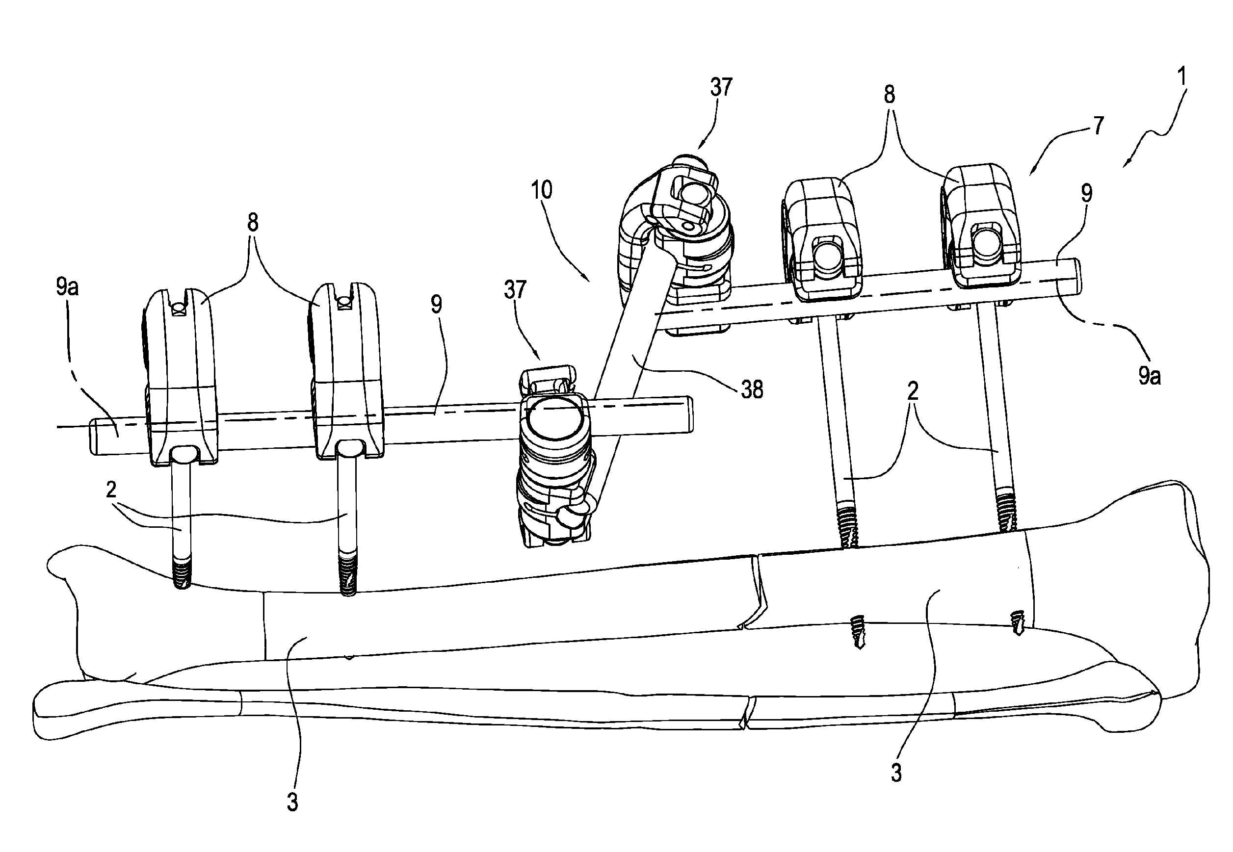
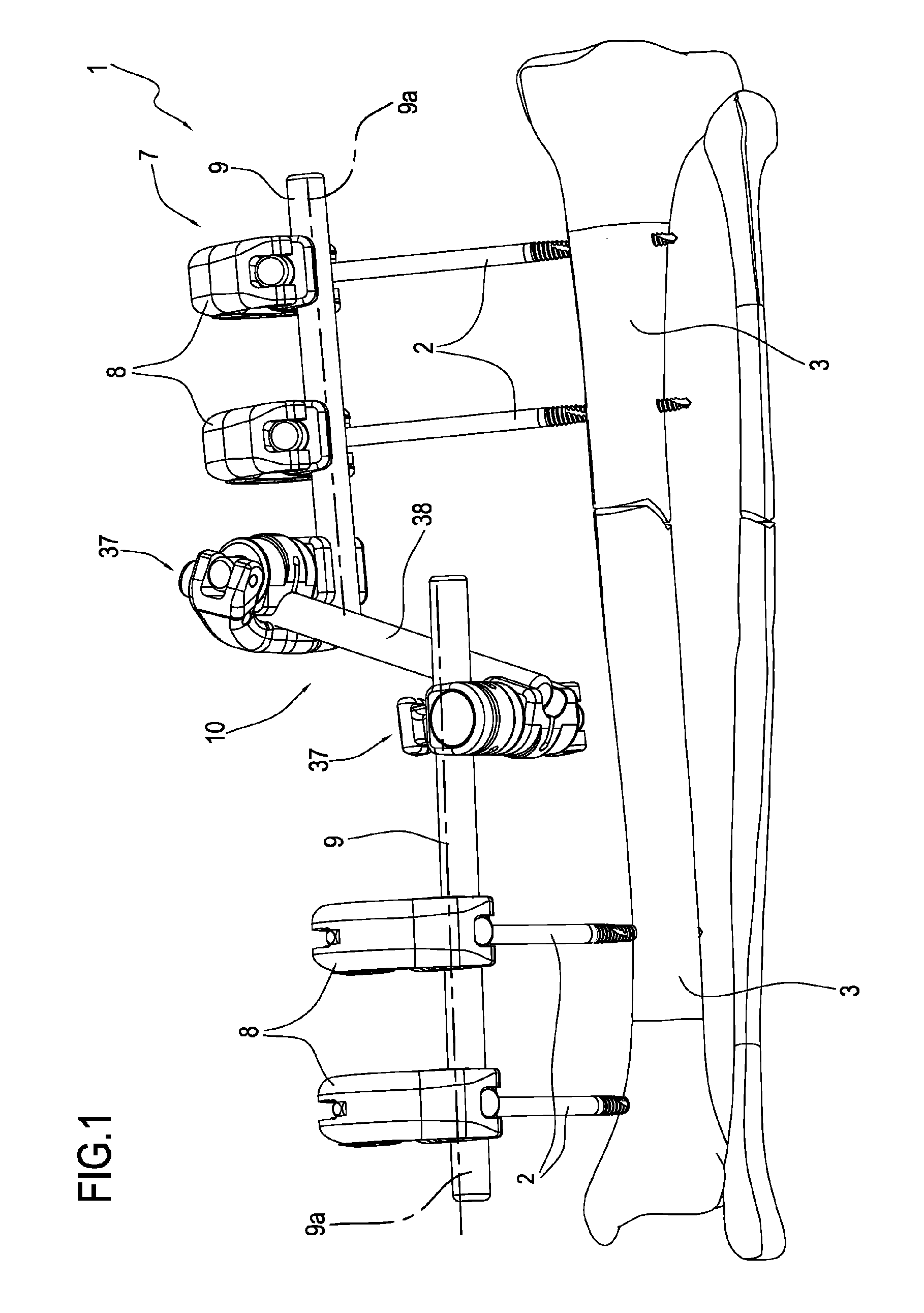
[0025]In FIG. 1 the numeral 1 denotes in its entirety a multi-purpose external fixator for orthopaedic use.

[0026]The fixator 1 may be used both to correct deformations caused by trauma and to correct pathological deformations. For example, the fixator 1 may be used to stabilise a fracture, or in other orthopaedic operations, such as limb lengthening, the correction of bone axis rotary and angular deformities, pseudarthrosis, etc.

[0027]The fixator 1 comprises at least one screw 2 to be implanted in a respective bone fragment 3. In particular, for each of the bone fragments 3 extending from the fracture fissure, the fixator 1 comprises at least two screws 2.

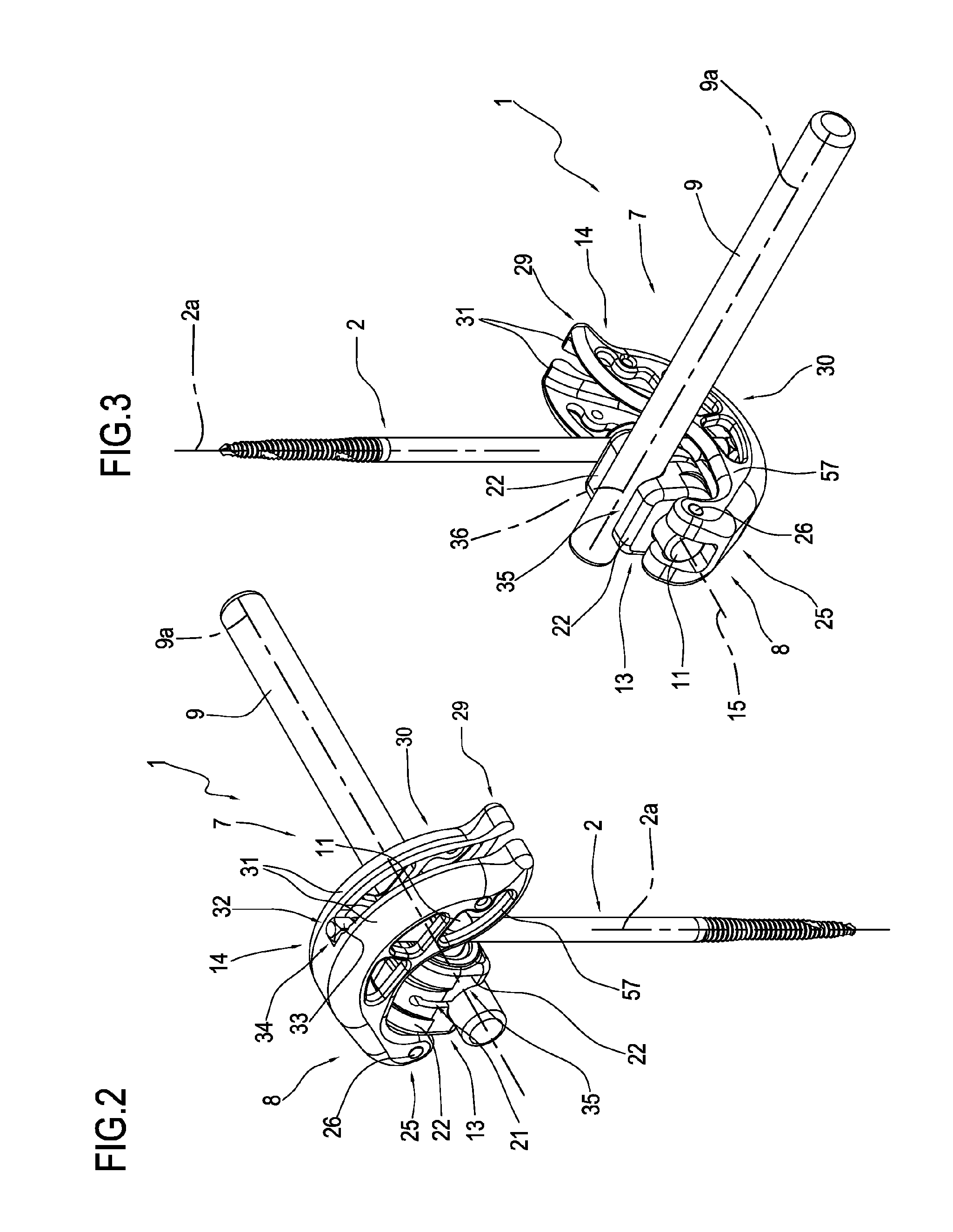
[0028]As FIG. 4 shows more clearly, each screw 2 comprises a cylindrical body 4, delimited on one side by a threaded end 5 designed to be screwed into the bone fragment 3, and on the other side by a head end 6.

[0029]Between the ends 5 and 6, the screw 2 extends along a longitudinal central axis 2a.

[0030]The fixator 1 also comprise...


PUM


Abstract

A multi-purpose external fixator (1) comprises at least one screw (2) to be implanted in a bone fragment (3) and a frame (7), in turn comprising at least one clamp (8) and at least one bar (9); the clamp (8) comprising a central body (11), in which a slot (12) is made for connection to the screw (2), an element (13) for locking the screw (2) in the slot (12) and a lever (14) for operating the locking element (13); the lever (14) is hinged to the central body (11) and can move away from and towards an end position for engagement of the locking element (13) and stable connection of the screw (2) to the slot (12); in the end position the lever (14) and the screw (2) are positioned in a T-shaped configuration relative to each other, in which the lever (14) forms a grip for implanting the screw (2) in the bone fragment.

Description

TECHNICAL FIELD[0001]This invention relates to a multi-purpose external fixator.BACKGROUND ART[0002]In orthopaedics, for several years a technique has been known for stabilising fractures without using external fixators instead of conventional plaster casts.[0003]External fixators usually comprise a plurality of bone screws, normally in pairs, which are implanted in the bone fragments of the fracture in such a way that the head ends of the screws project from the skin of the patient. Said ends are anchored to a rigid external frame which is equipped with clamps and joints which can be orientated in such a way as to allow them to be adjusted to the position of the screws.[0004]The screws usually have a cylindrical body, delimited on one side by a threaded end designed to be screwed into the bone fragment, and on the other side by the above-mentioned head end, which is shaped in such a way that it can be connected to a temporary grip which allows the screw to be screwed into the bone ...

Claims


Application Information

Patent Timeline
Patent Type & Authority Applications(United States)
IPC IPC(8): A61B17/64
CPCA61B17/6466A61B17/6416
Inventor MINGOZZI, FRANCODOVESI, ALAN
Owner CITIEFFE
Learn More