
Recoil System and Method for Upper Receiver

Active Publication Date: 2012-08-16
THE OTIS PATENT TRUST
View PDF3 Cites 35 Cited by
  • Summary
  • Abstract
  • Description
  • Claims
  • Application Information

AI Technical Summary

Benefits of technology

[0003]In embodiments, this new system and method would allow for the M16 / M4 rifle system in 5.56 mm / .223 caliber and the AR10 / SR25 rifle system in 7.62 mm / .308 caliber, among other possible rifle systems, to have a folding stock capability. There have been previous folding stock rifle designs, but such designs used a recoil spring housed around the gas tube, which allows heat transfer from the gas tube to the spring and causes weakening of the spring. In embodiments, this new system and method uses a recoil spring and rod housed inside the upper receiver sitting above the bolt carrier. The recoil spring / rod is contained in a housing that sits on top of the bolt carrier. This housing is designed in such a way that it not only still allows the use of direct gas impingement design of the M16-style rifle but also prevents transfer of heat from the gas tube to the recoil spring.
[0005]In embodiments, the system and method comprise a spring rod with a retaining tab attached to the rear portion of the rod. This tab allows for the break down of the rifle for cleaning by simply pressing the tab forward a short distance, which allows the rear of the break down tab to release itself from the lower receiver.
[0006]In embodiments, this system and method give a distinct advantage to mounted troops and aviation crews where a compact weapon is needed and this system allows for a folding or other type of non-fixed stock because there is no need for a recoil spring / buffer / buffer tube to be housed in the butt stock straight in-line with the barrel. This reduces overall length of the rifle, bringing the overall length of the rifle in embodiments down to around 22″ with a 12″ barrel.

Problems solved by technology

There have been previous folding stock rifle designs, but such designs used a recoil spring housed around the gas tube, which allows heat transfer from the gas tube to the spring and causes weakening of the spring.

Method used


Image

  • Recoil System and Method for Upper Receiver
  • Recoil System and Method for Upper Receiver
  • Recoil System and Method for Upper Receiver

Examples


Embodiment Construction

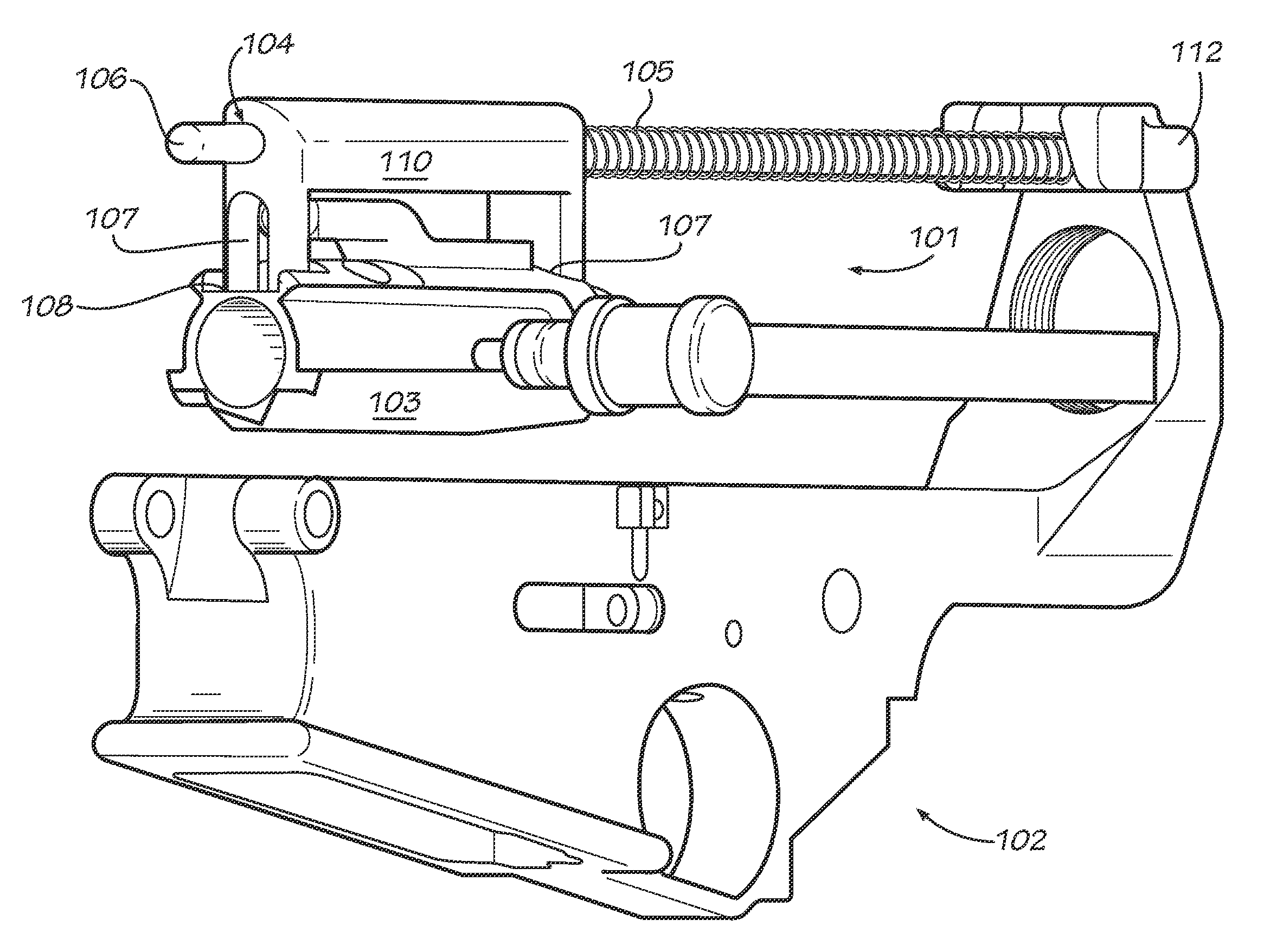
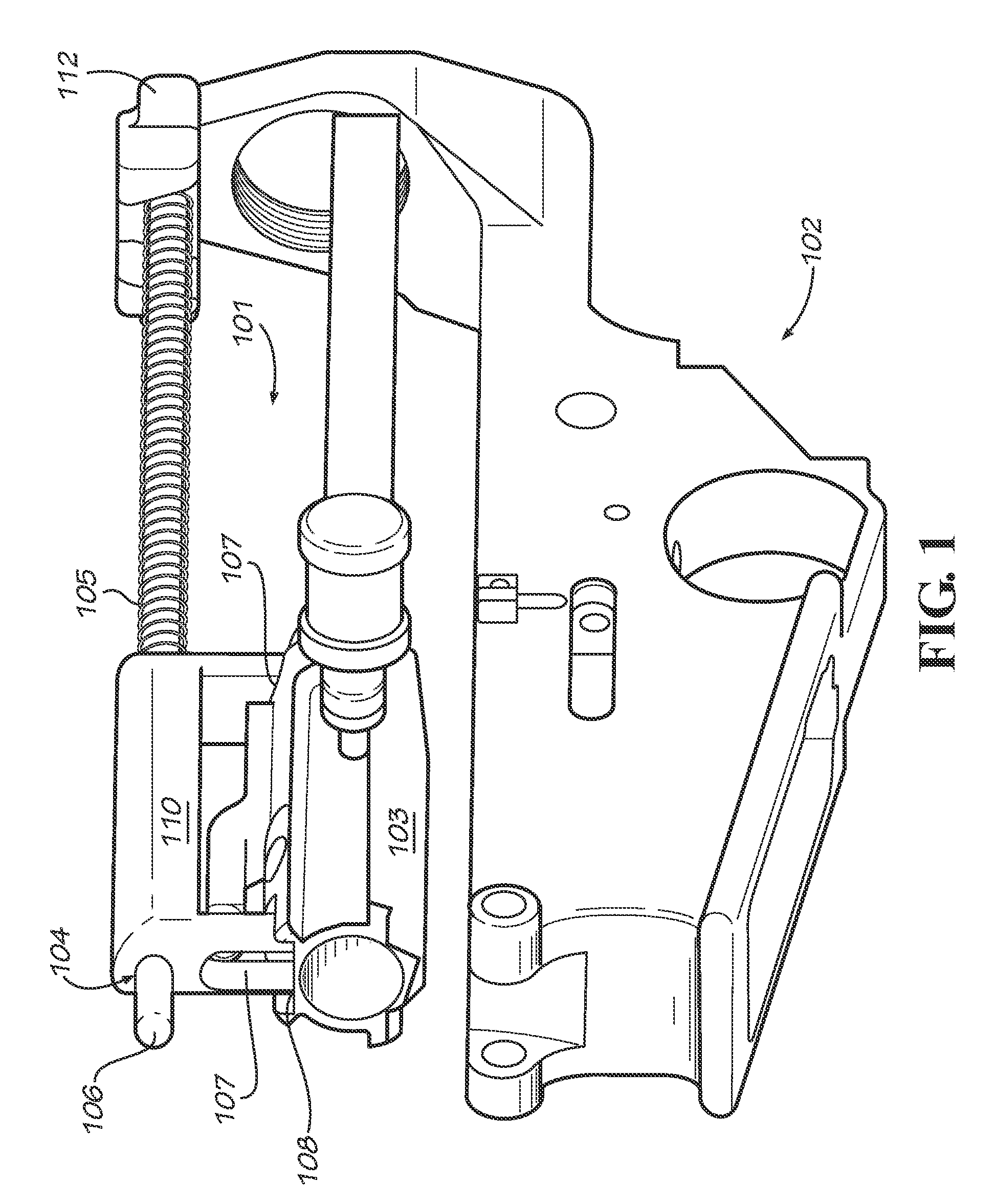
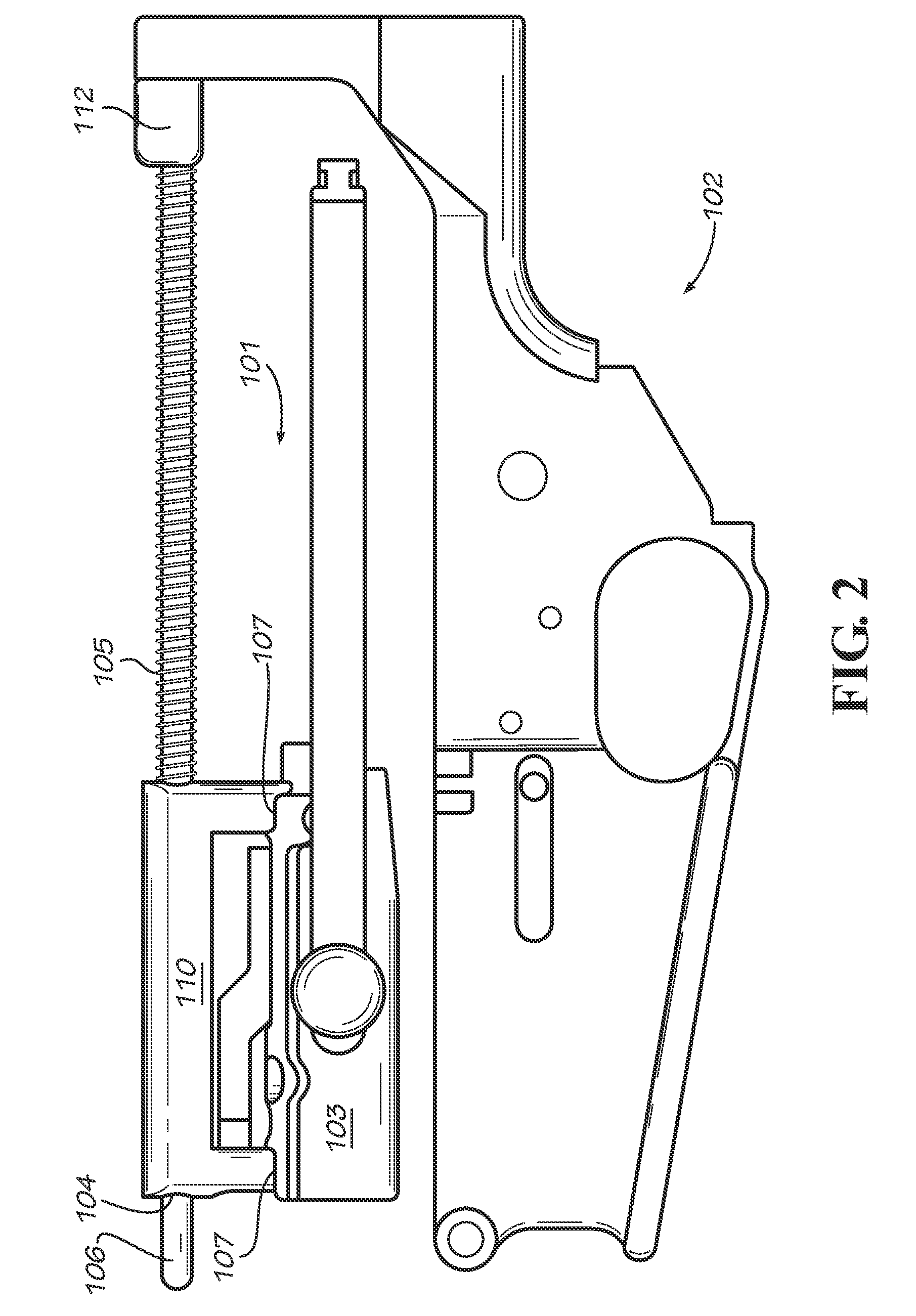
[0013]Disclosed below are embodiments of a modular rifle system and method having a folding or non-fixed stock capability. FIG. 1 is a perspective view of an upper receiver assembly 101 along with a lower receiver assembly 102 in accordance with one exemplary embodiment of the present invention. Upper receiver 101 is releasably coupled to lower receiver 102. Upper receiver 101 contains a bolt carrier 103.

[0014]With reference to FIG. 1, upper receiver 101 contains a housing 110. Housing 110 encloses a recoil spring 105 and rod 106. Bolt carrier 103 contains integrated receptacle compartments in its top face, which allow housing 104 to be mounted on and rest upon bolt carrier 103 inside upper receiver 101. Within housing 110, recoil spring 105 rests against a counter bore shoulder. The front of housing 110 contains a hole 104 through which rod 106 protrudes, and upper receiver 101 also contains a hole through which rod 106 protrudes. In this embodiment, relocating the recoil spring an...


PUM

PropertyMeasurementUnit
Lengthaaaaaaaaaa
Lengthaaaaaaaaaa
Lengthaaaaaaaaaa

Abstract

In embodiments, a modular rifle includes a lower receiver assembly, an upper receiver assembly, and a coupling mechanism. The upper receiver contains a bolt carrier and a housing enclosing the recoil spring and rod. Within the housing is a counter bore shoulder against which the recoil spring rests. Integrated into the top face of the bolt carrier are compartments, upon which the housing is mounted. Holes in the front of the housing and the upper receiver assembly accommodate the rod. Containing the recoil spring and rod within in the housing mounted to the bolt carrier allows the modular rifle to have a folding, collapsible, or otherwise non-fixed stock. Attached to the rod is a retaining tab, the depression of which allows for the release of the upper receiver from the lower receiver for disassembly of the rifle.

Description

PRIORITY[0001]This application claims priority from the provisional application filed Feb. 11, 2011, with Ser. No. 61 / 441,688 and entitled “Recoil System and Method for Upper Receiver,” which is incorporated herein by reference in its entirety.BACKGROUND OF THE INVENTION[0002]The M16-style rifle is a type of modular rifle system commonly used by military and police forces that features a gas-operated bolt and bolt carrier system, as disclosed, for example, in U.S. Pat. No. 2,951,424, issued to Eugene M. Stoner on Sep. 6, 1960 (incorporated herein by reference in its entirety). A modular rifle typically includes a lower receiver assembly, and upper receiver assembly, and a coupling mechanism. Two types of M-16-style rifle are the M16 / M4 rifle system in 5.56 mm / .223 caliber and the AR10 / SR25 rifle system in 7.62 mm / .308 caliber. The M16 / M4 rifle system in 5.56 mm / .223 caliber and the AR10 / SR25 rifle system in 7.62 mm / .308 caliber each utilize direct gas operation with a traditional, n...

Claims


Application Information

Patent Timeline
IPC IPC(8): F41A3/82F41C7/00F41C23/04B23P11/00
CPCF41A3/66Y10T29/49826F41A3/82
Inventor PATEL, SWETAL K.
Owner THE OTIS PATENT TRUST
Features
  • Generate Ideas
  • Intellectual Property
  • Life Sciences
  • Materials
  • Tech Scout
  • Unparalleled Data Quality
  • Higher Quality Content
  • 60% Fewer Hallucinations
Learn More