
Float device

a float device and float technology, applied in the direction of underwater vessels, volume measurement, height/levelling measurement, etc., can solve the problem that the buoyant force is difficult to be controlled with high accuracy, and achieve the effect of reducing the number of parts, high accuracy, and controlling the buoyant for

Active Publication Date: 2012-08-16
TSURUMI SEIKI +1
View PDF0 Cites 13 Cited by
  • Summary
  • Abstract
  • Description
  • Claims
  • Application Information

AI Technical Summary

Benefits of technology

The present invention provides a float device that can control its buoyant force with high accuracy during both ascent and descent. The device includes a float hull, a drive motor, a plunger, an internal oil reservoir, an externally-opened cylinder, a buoyant force adjustment piston, and a three-way valve. The three-way valve has three connection ports that switch the flow between them. The device can reduce the number of parts and the size of the float hull.

Problems solved by technology

The buoyant force adjustment mechanism can be controlled by the plunger during the ascent but cannot be controlled by the plunger during the descent, and thus there is a problem that the buoyant force is difficult to be controlled with high accuracy.

Method used


Image

  • Float device
  • Float device
  • Float device

Examples


Embodiment Construction

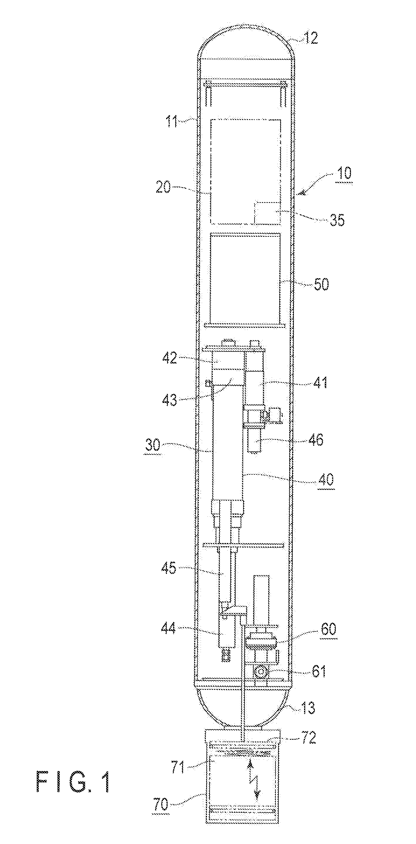
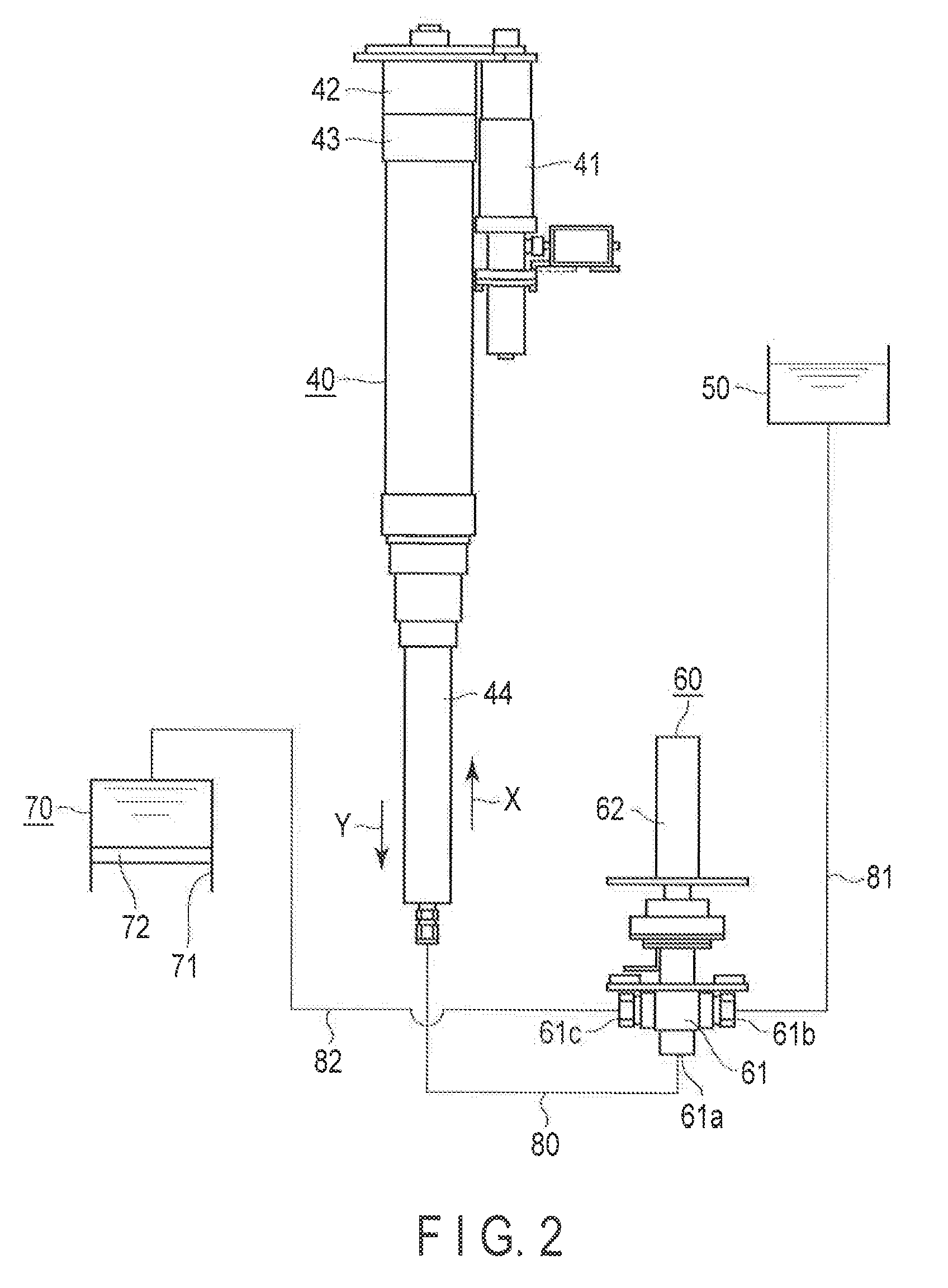
[0019]FIG. 1 is a diagram showing an ocean observation float device 10 according to one embodiment of the present invention, and FIG. 2 is an explanatory diagram schematically showing a buoyant force adjustment mechanism 30 incorporated in the ocean observation float device 10.

[0020]The ocean observation float device 10 comprises a float hull 11 formed in a cylinder-like shape. The float hull 11 is provided with a hollow or the like inside or outside, and is set to have a predetermined buoyant force. An electronic part mounting unit 20 mounting an antenna for transmission and reception with external communication devices, and various ocean observation electronic devices thereon is mounted on a top part 12 of the float hull 11. Part of the buoyant force adjustment mechanism 30 is mounted on a bottom part 13 of the float hull 11.

[0021]The buoyant force adjustment mechanism 30 comprises a plunger mechanism 40 arranged inside the float hull 11, an internal oil reservoir 50 for storing a...


PUM


Abstract

A float device includes a drive motor provided inside a float hull, a plunger reciprocating along with rotation of the drive motor, an internal oil reservoir for housing an hydraulic oil therein, an externally-opened cylinder attached to the float bull, a buoyant force adjustment piston reciprocating in the cylinder along with exit / entry of the hydraulic oil, and a three-way valve having a first connection port connected to the plunger, a second connection port connected to the internal oil reservoir, and a third connection per connected to the cylinder, for switching the flow between the first connection port and the second connection ports and the flow between the first connection port and the third connection port.

Description

CROSS REFERENCE TO RELATED APPLICATIONS[0001]This application is a Continuation Application of PCT Application No. PCT / JP2010 / 069089, filed Oct. 27, 2010 and based upon and claiming the benefit of priority from prior Japanese Patent Application No. 2009-246472, filed. Oct. 27, 2009, the entire contents of all of which are incorporated herein by reference.BACKGROUND OF THE INVENTION[0002]1. Field of the Invention[0003]The present invention relates to a float device such as ocean observation float device, which is called a “profiling float” used for an ocean monitoring system (which will be called Argo program below), and particularly to a technique capable of reducing the number of parts and adjusting a buoyant force with high accuracy.[0004]2. Description of the Related Art[0005]In order to address the environmental problems such as global warming, it is necessary to reveal environmental variation mechanisms in the global environment and to determine the total amount and the circula...

Claims


Application Information

Patent Timeline
Patent Type & Authority Applications(United States)
IPC IPC(8): B63B22/08
CPCB63B2211/02B63G8/24B63G8/22B63B22/20
Inventor WATANABE, KAZUHIROSHIKAMA, NOBUYUKIMIZUNO, KEISUKE
Owner TSURUMI SEIKI
Learn More