

HVAC system for a work vehicle
a technology for work vehicles and heaters, applied in vehicle maintenance, vehicle cleaning, roofs, etc., can solve the problems of adding additional heaters to the work vehicl
- Summary
- Abstract
- Description
- Claims
- Application Information
AI Technical Summary
Benefits of technology
Problems solved by technology
Method used
Image


Examples
Embodiment Construction
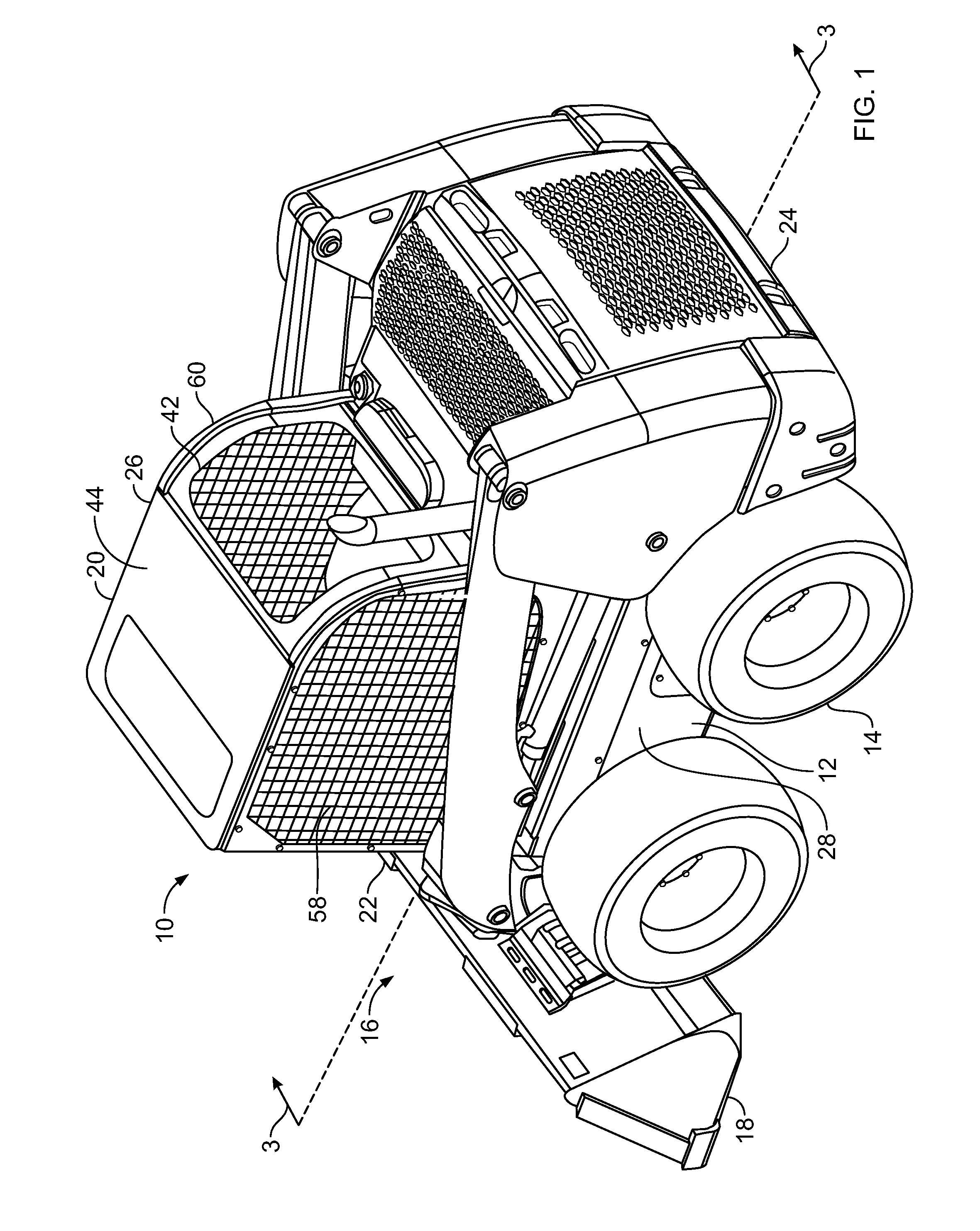
[0015]FIG. 1 shows a work vehicle 10 provided with a frame 12 that rotatably carries a driving device 14, such as a plurality of wheels, although in another embodiment, tracks may be used or activated to selectably move the vehicle. A lifting structure 16 includes an arrangement of structural members and actuators controllable by an operator (not shown) to manipulate an implement 18 to perform work. Frame 12 structurally supports an operator cab 20 or cab to surround and protect the operator, which frame 12 includes a front end 22 facing implement 18 and an opposed back end 24 with ends 22, 24 positioned between opposed lateral sides 26, 28 of the frame.
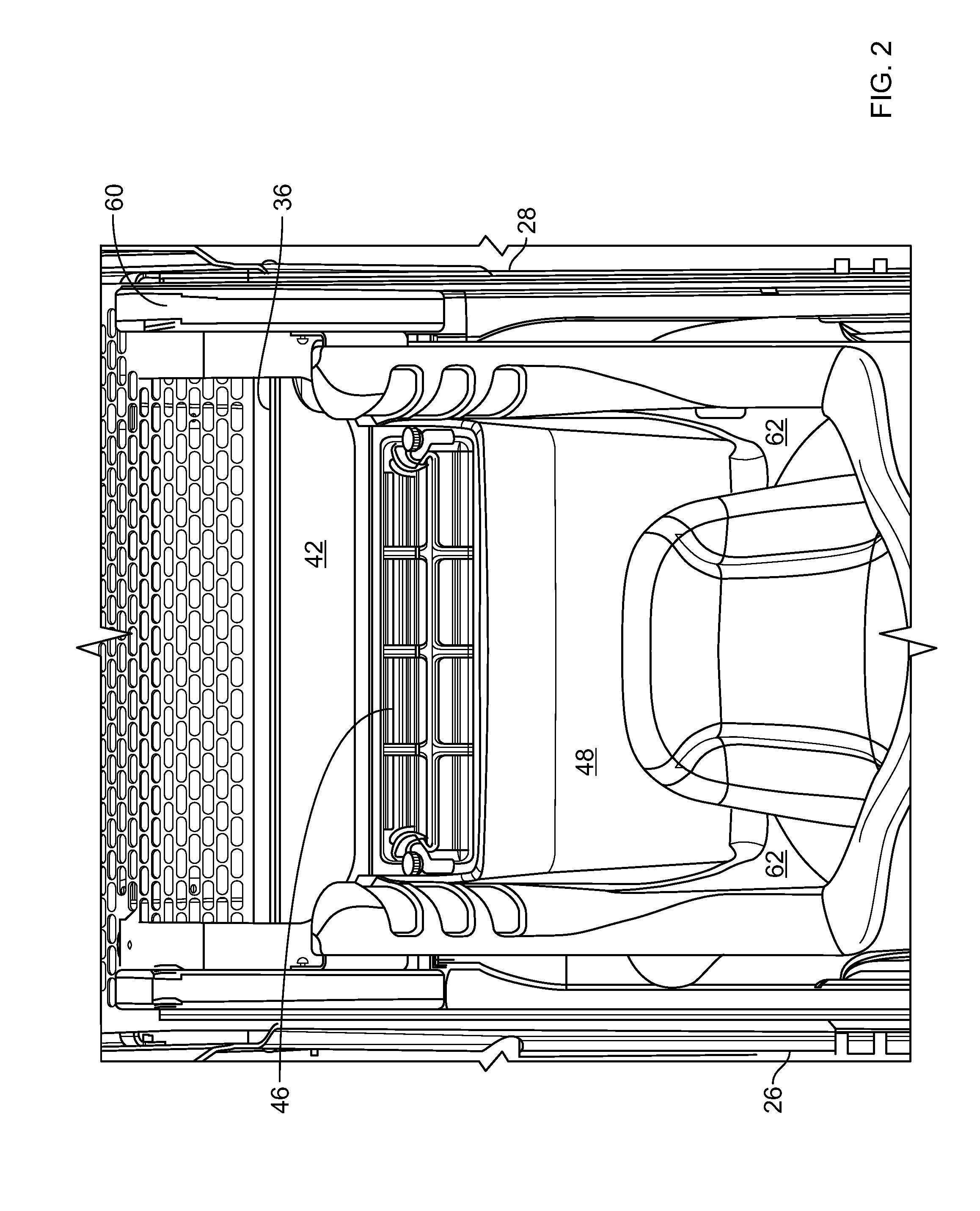
[0016]FIGS. 2-3 show different views of cab 20 and associated structure. Cab 20 includes an HVAC system 30 to provide environmental comfort to an operator positioned within the cab. In addition, HVAC system 30, in combination with unique structural features of cab 20, provides a recirculating airflow 54 sufficient to remove a non-tra...
PUM
 Abstract
Description
Claims
Application Information