Image display apparatus and control method thereof

a technology of image display and control method, applied in the field of image display apparatus, can solve the problems of inability to achieve desired effect, inability to display an image correctly and stably over the entire screen, etc., and achieve the effect of appropriate control of the luminance of the display screen

Inactive Publication Date: 2012-08-16
CANON KK
View PDF8 Cites 23 Cited by
  • Summary
  • Abstract
  • Description
  • Claims
  • Application Information

AI Technical Summary

Benefits of technology

[0015]According to the present invention, it is possible to appropriately control luminance of the display screen according to the temperature characteristics of each area of the screen of an image display apparatus.

Problems solved by technology

However, in the technique of Japanese Patent Laid-Open No. 2008-046289 stated above, since the liquid crystal driving amount is controlled by using only the temperature rising characteristics associated with a specific state which is defined in terms of elapsed time after start up, there may be cases where a desired effect cannot be achieved if the apparatus is not in that specific state.
In conventional techniques, no consideration is given to the case where the temperature characteristics differ among areas in the screen of the display apparatus, and thus there are cases in which it is impossible to display an image correctly and stably over the entire screen.

Method used


Image

  • Image display apparatus and control method thereof
  • Image display apparatus and control method thereof
  • Image display apparatus and control method thereof

Examples


embodiment 1

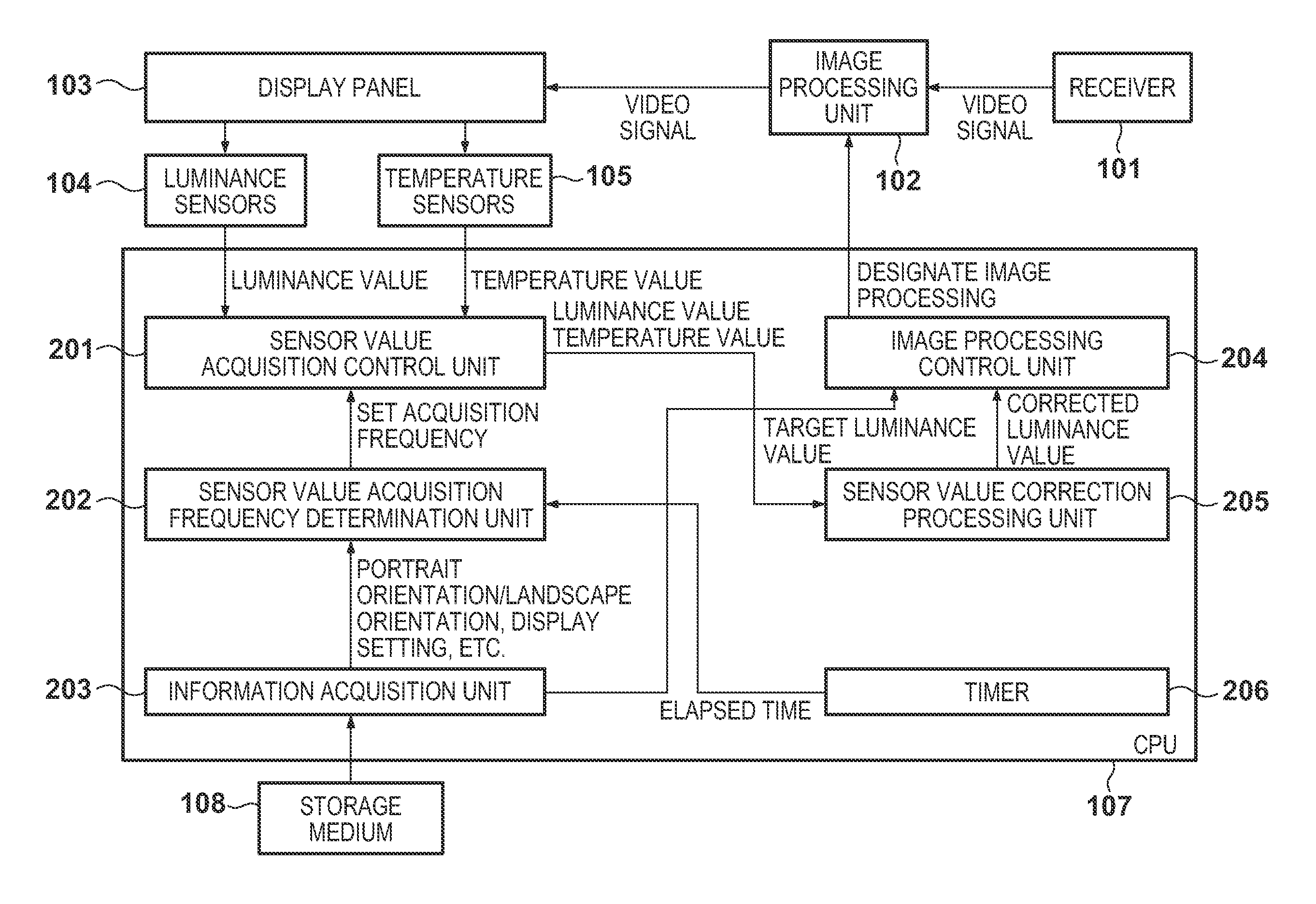
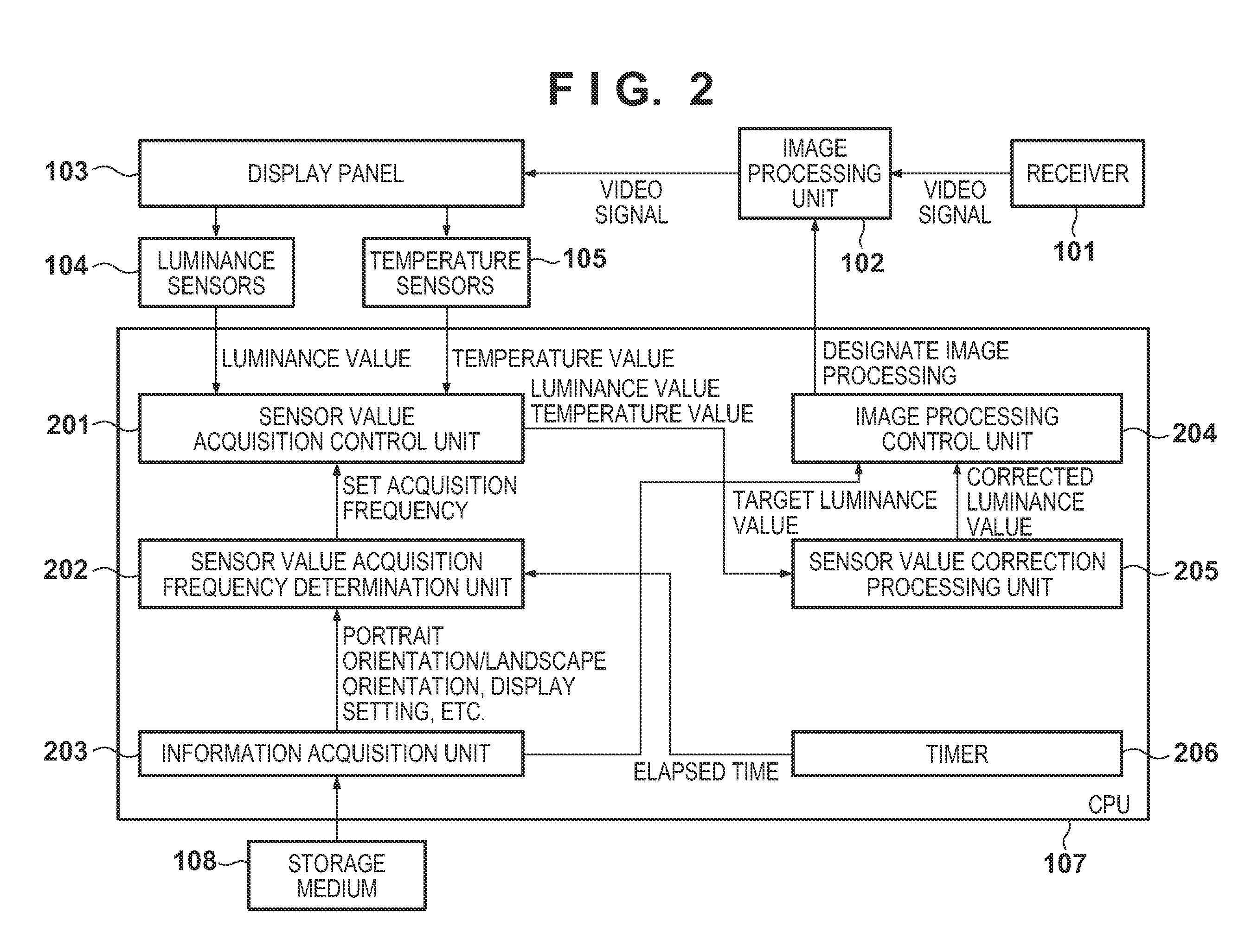
[0036]As Embodiment 1, an image display apparatus will be described that performs feedback control for setting the luminance of the display unit to a target luminance value, by using luminance information of the display unit detected by the luminance sensors. Here, the luminance sensor mounted to the image display apparatus has temperature characteristics, and thus the value detected by the luminance sensor varies depending on the ambient temperature. Therefore, the image display apparatus also includes a temperature sensor to correct the values detected by the luminance sensor. In Embodiment 1, the sensor value acquisition frequency is changed between when the image display apparatus is installed in the portrait orientation and when it is installed in the landscape orientation.

Configuration of Apparatus

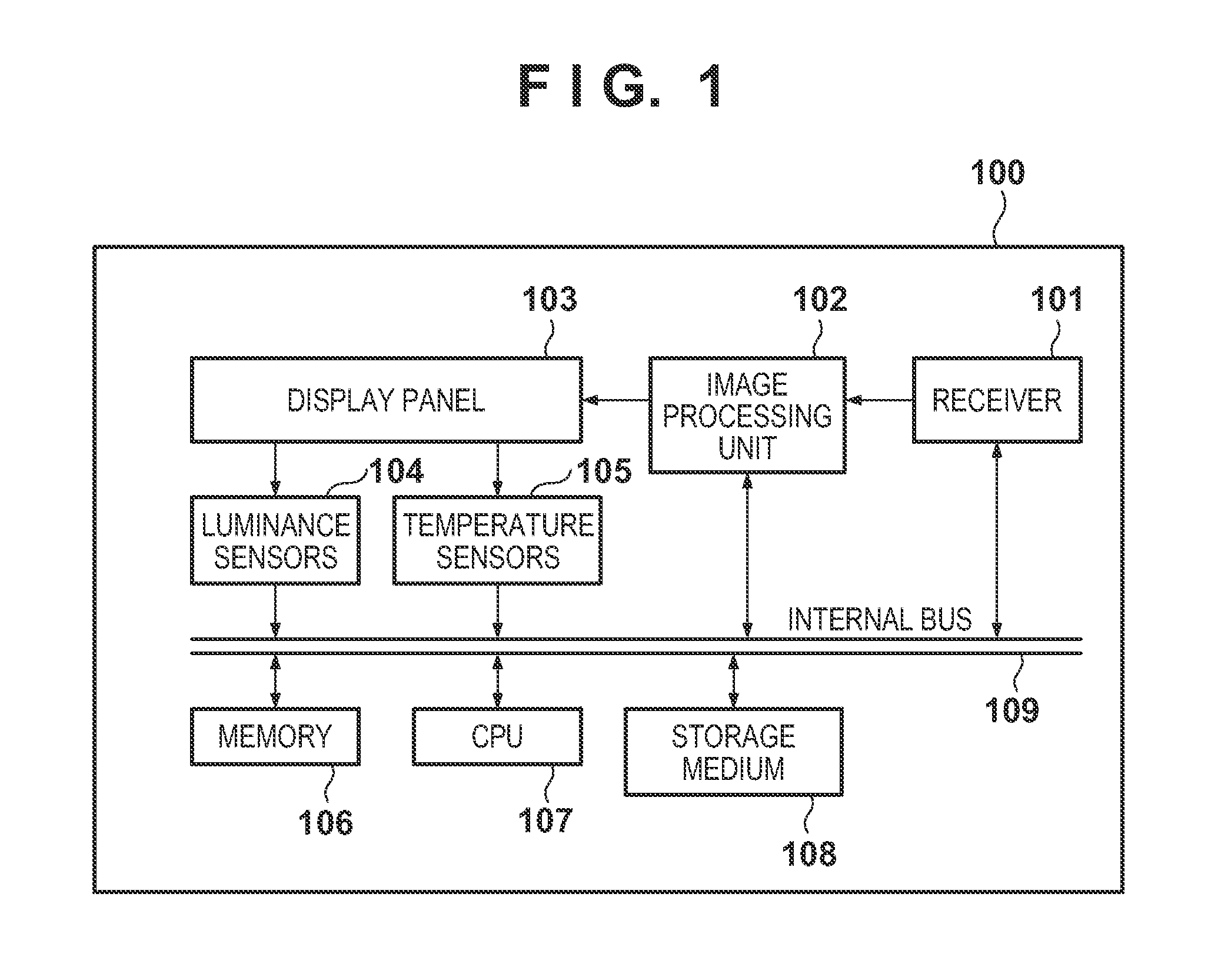
[0037]The configuration of the image display apparatus will be described below with reference to FIG. 1.

[0038]In FIG. 1, a receiver 101 receives video signals input to an image displ...

embodiment 2

[0089]Embodiment 2 is an example in which in the case where, in a multi-screen display mode in which the display panel 103 of the image display apparatus 100 is divided into a plurality of areas for display, image processing settings differ for each screen, the acquisition frequencies for the temperature sensors 105 are varied. Note that since the hardware configuration and the functional block configuration for realizing Embodiment 2 are same as those of Embodiment 1, description thereof is omitted here.

[0090]Processing in which the acquisition frequency determination unit 202 determines the sensor value acquisition frequency after start-up of an image display apparatus 100 in Embodiment 2 will be described with reference to FIG. 12.

[0091]In FIG. 12, after the image display apparatus 100 is started up, in step S1201, the information acquisition unit 203 reads out a variety of information of the image display apparatus 100. Here, the display panel 103 of the image display apparatus ...


PUM


Abstract

An image display apparatus, comprises a display unit; a luminance sensor arranged in plural portions of the display unit, each luminance sensor having temperature characteristics; a temperature sensor arranged in plural portions of the display unit; an acquisition control unit configured to acquire a temperature value from the temperature sensor and a luminance value from the luminance sensor; a determination unit configured to determine a frequency for acquiring the temperature value from the temperature sensor based on an orientation of the display unit or a display setting; a correction unit configured to correct the luminance value acquired from the luminance sensor by using the temperature value acquired from the temperature sensor; and an image processing unit configured to control luminance of the display unit by using the luminance value corrected by the correction unit as a target luminance value.

Description

BACKGROUND OF THE INVENTION[0001]1. Field of the Invention[0002]The present invention relates to an image display apparatus that displays video signals.[0003]2. Description of the Related Art[0004]Recently, liquid display apparatuses have become mainstream in image display apparatuses. In a liquid crystal display apparatus, a light source (hereinafter referred to as the “back light”) emits light from the rear face of a liquid crystal panel and transmitted light is observed, thereby displaying an image.[0005]With respect to the liquid crystal panel, which is an element constituting the liquid crystal display apparatus, there is a correlation between the liquid crystal driving amount and the temperature of the liquid crystal panel. The light-emitting diode (hereinafter referred to as the “LED”), which is becoming a mainstream in back lights, a luminance sensor mounted for performing feedback control on luminance and colors, and the like also have temperature characteristics. Therefore...

Claims


Application Information

Patent Timeline
Patent Type & Authority Applications(United States)
IPC IPC(8): G09G3/36G09G5/10
CPCG09G3/3426G09G2320/0233G09G2360/145G09G2320/0626G09G2360/144G09G2320/041
Inventor SAKAKIMA, EITOTAMURA, MASAKI
Owner CANON KK
Why Eureka
Try Eureka