
Load-Balancing Structure for Packet Switches with Minimum Buffers Complexity and its Building Method

a packet switch and buffer complexity technology, applied in the field of communication, can solve the problems of limited internal capacity of the switching structure, different traffic, and different size of the mid-stage voq, and achieve the effect of reducing the buffer complexity to o(n) and improving the end-to-end throughpu

Inactive Publication Date: 2012-08-16
PEKING UNIV SHENZHEN GRADUATE SCHOOL +1
View PDF3 Cites 7 Cited by
  • Summary
  • Abstract
  • Description
  • Claims
  • Application Information

AI Technical Summary

Benefits of technology

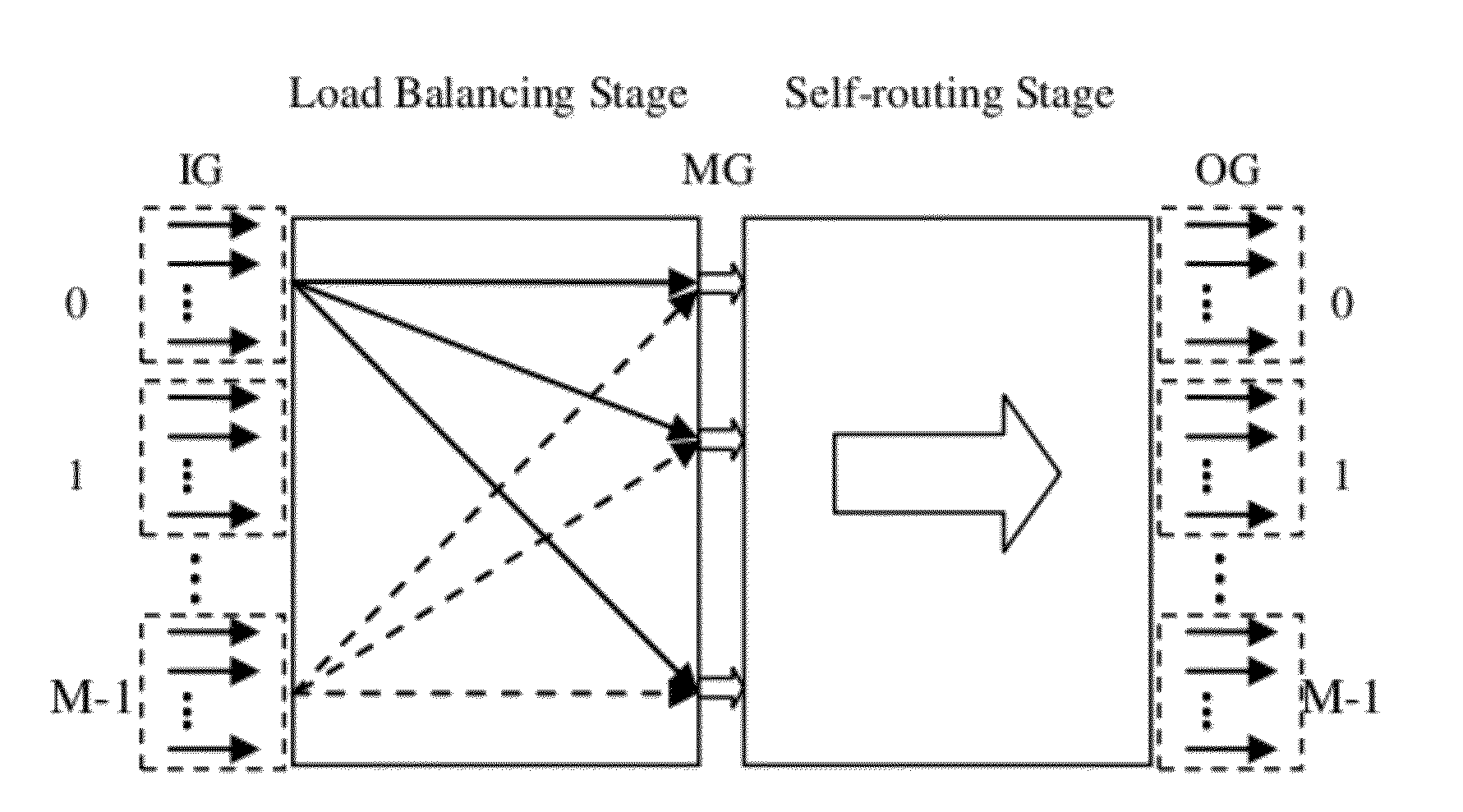
[0007]The present invention provides a structure of load-balancing packet switches and its concomitant methodology which solves the problem of packets out-of-sequence to improve end-to-end throughput and to greatly reduce the complexity of buffers.
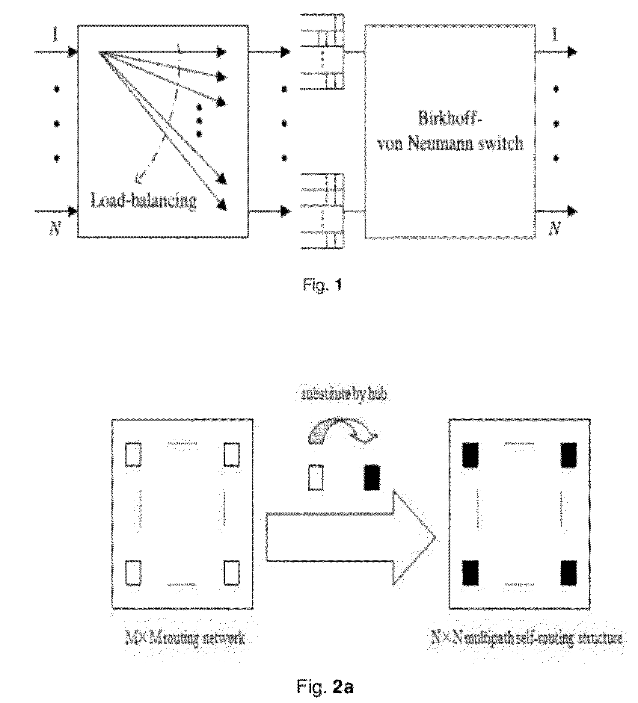
[0021]Comparing this structure with the LB-BvN, it is clear that this invention of load-balancing packet switches with minimum buffers complexity and its concomitant methodology abandons the VOQ between the first stage and the second stage fabrics, which has no problems of queuing delay and packets out-of-sequence. Therefore, this invention solves the problem of packets out-of-sequence in load-balancing Birkhoff-von Neumann switching structure and improves the end-to-end throughput. Moreover, it greatly reduces the buffer complexity to O(N).

Problems solved by technology

As internal capacity in switching structure is limited, some ports or internal lines become saturation while others are still in idle state when traffic arriving switching structure is unbalanced.
However, traffic is different and unbalance for each input port, the number of packets belongs to different flows is variable, so the size of mid-stage VOQ is also different.
As queues are served uniformly independent of their sizes, this LB-BvN structure brings about problems such as queuing delay and packets out-of-sequence.
Moreover, because of adopting VOQ, the complexity of packet buffers is at least O(N2).
As the switching scale increases, the hardware implementation and cost become unrealistic.
Hence, these properties make it unsuitable for very large scale switching structures.

Method used


Image

  •  Load-Balancing Structure for Packet Switches with Minimum Buffers Complexity and its Building Method
  •  Load-Balancing Structure for Packet Switches with Minimum Buffers Complexity and its Building Method
  •  Load-Balancing Structure for Packet Switches with Minimum Buffers Complexity and its Building Method

Examples


Embodiment Construction

[0032]Below is a detailed description of the invention through a better implementation way, and it is not used to restrict the invention. For any revise, identical substitute by any general technical personnel in this field should be protected.

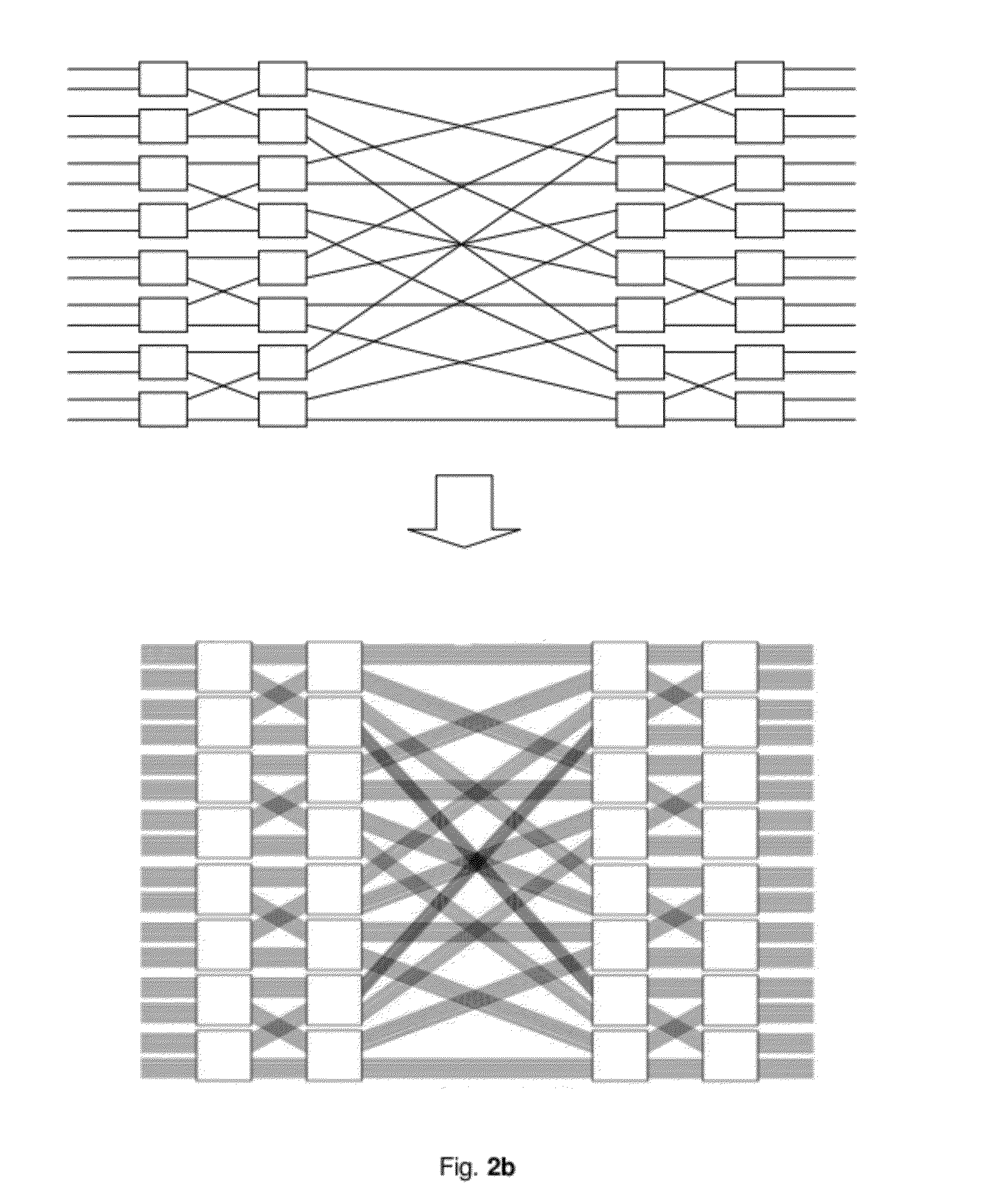
[0033]The invention which is based on self-routing concentrators provides a packet switching structure, and the structure which mainly uses concentrators and line group technology can be constructed based on the routable multi-stage interconnect network (MIN).

[0034]The invention provides a method for constructing a load-balancing packet switching structure with minimum buffer complexity. The method comprises: S1: Dividing the structure which is based on self-routing concentrators into a two-stage switching fabric. The first stage accomplishes the function of load balancing and the second stage self-routes and forwards the incoming data. S2: Appending a packet aggregated splitter (PAS) and an Input aggregating ring queue (IARQ) at each of the i...


PUM


Abstract

This invention provides a structure of load-balancing packet switches with minimum buffers complexity and its concomitant methodology. It abandons the VOQ between the first stage and the second stage fabrics, which has no problems of queue delay and packets out-of-sequence. Therefore, this invention solves the packets out-of-sequence problem in load-balancing Birkhoff-von Neumann switching structure and improves the end-to-end throughput. Moreover, it greatly reduces the buffer complexity to O(N).

Description

TECHNICAL FIELD OF THE INVENTION[0001]This invention relates to communication and, more particularly, to a structure of load-balancing packet switches with minimum buffers complexity and its concomitant methodology.BACKGROUND OF THE INVENTION[0002]The so-called switching structure, in the application of telecommunications, is a kind of network equipment which achieves routing for data units and forwards them to the next hop node.[0003]As internal capacity in switching structure is limited, some ports or internal lines become saturation while others are still in idle state when traffic arriving switching structure is unbalanced. In order to avoid unbalanced traffic, load-balancing switching structure is used to solve this problem. The structure makes traffic uniformly distributed inside of it, that is, the utilization of all ports and internal lines are identical. Such switching structure can improve throughput to the maximum extent and decrease the internal blocking.[0004]The struct...

Claims


Application Information

Patent Timeline
Patent Type & Authority Applications(United States)
IPC IPC(8): H04L12/26
CPCH04L47/125H04L47/34H04L47/30H04L47/193
Inventor LI, HUILI, SHUOYANLIN, LIANGMINLI, RUIYUANAN, HUIYAOLI, FENGCHEN, QINSHUZHANG, MINGLONGCHEN, XI
Owner PEKING UNIV SHENZHEN GRADUATE SCHOOL
Learn More