
Method of notifying resource allocation for demodulation reference signals

a reference signal and resource allocation technology, applied in the field of cellular mobile communication system, can solve the problems of inconvenient multi-user mimo scheduling and power allocation, difficult to maintain a fixed offset between the power of dmrs and the power of downlink data, and a lot of inconvenience for multi-user power allocation, so as to suppress or cancel interference

Active Publication Date: 2012-08-16
SHARP KK
View PDF8 Cites 77 Cited by
  • Summary
  • Abstract
  • Description
  • Claims
  • Application Information

AI Technical Summary

Benefits of technology

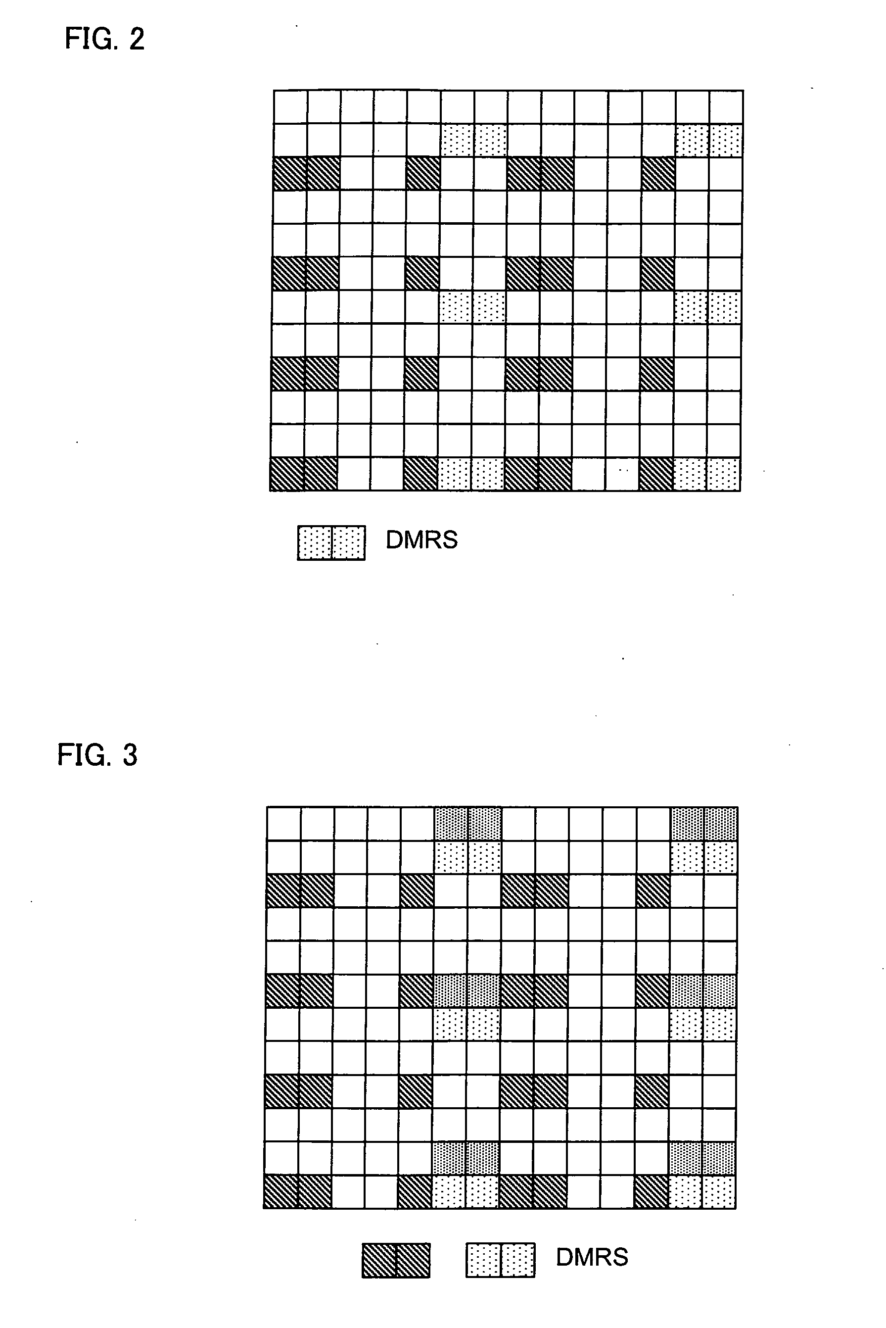
[0020]Preferably, the user equipment detects, in its own frequency band, a reception power or correlation for its unused DMRS antenna port to determine whether the DMRS antenna port is allocated to another user equipment; and performs, when a DMRS antenna port is determined as being allocated to another equipment, channel estimation on the DMRS antenna port to suppress or cancel interference from the another user equipment corresponding to the DMRS antenna port.

Problems solved by technology

However, this causes some inconvenience for multi-user MIMO scheduling and power allocation.
In a DMRS design, however, there are a plurality of multiplexing approaches such as Frequency Division Multiplexing (FDM) and Code Division Multiplexing (CDM), such that it is difficult to maintain a fixed offset between the power of DMRS and the power of downlink data.
Thus, the base station is still required to signal to the UE a power ratio between the DMRS and the downlink data, which causes a lot of inconveniences for multi-user power allocation in a Multi-User Multiple Input Multiple Output (MU-MIMO) mode.
In the MU-MIMO operation mode, different DMRS resources used by the individual UEs will result in a large amount of combinations and an increased system signaling overhead on the downlink.

Method used


Image

  • Method of notifying resource allocation for demodulation reference signals
  • Method of notifying resource allocation for demodulation reference signals
  • Method of notifying resource allocation for demodulation reference signals

Examples


Embodiment Construction

[0040]Some particular embodiments of the present invention will be described in the following such that the implementation steps of the present invention can be clearly detailed. While these embodiments are directed to a mobile communication system utilizing a dedicated DMRS on downlink (particularly an LTE-Advanced cellular mobile communication system), it is to be noted that the present invention is not limited to these applications and can be applied to other related communication systems.

[0041]In the following, the preferred embodiments of the present invention will be detailed with reference to the figures. In the present description, details and functions unnecessary for the present invention will be omitted, so as not to obscure the understanding the present invention.

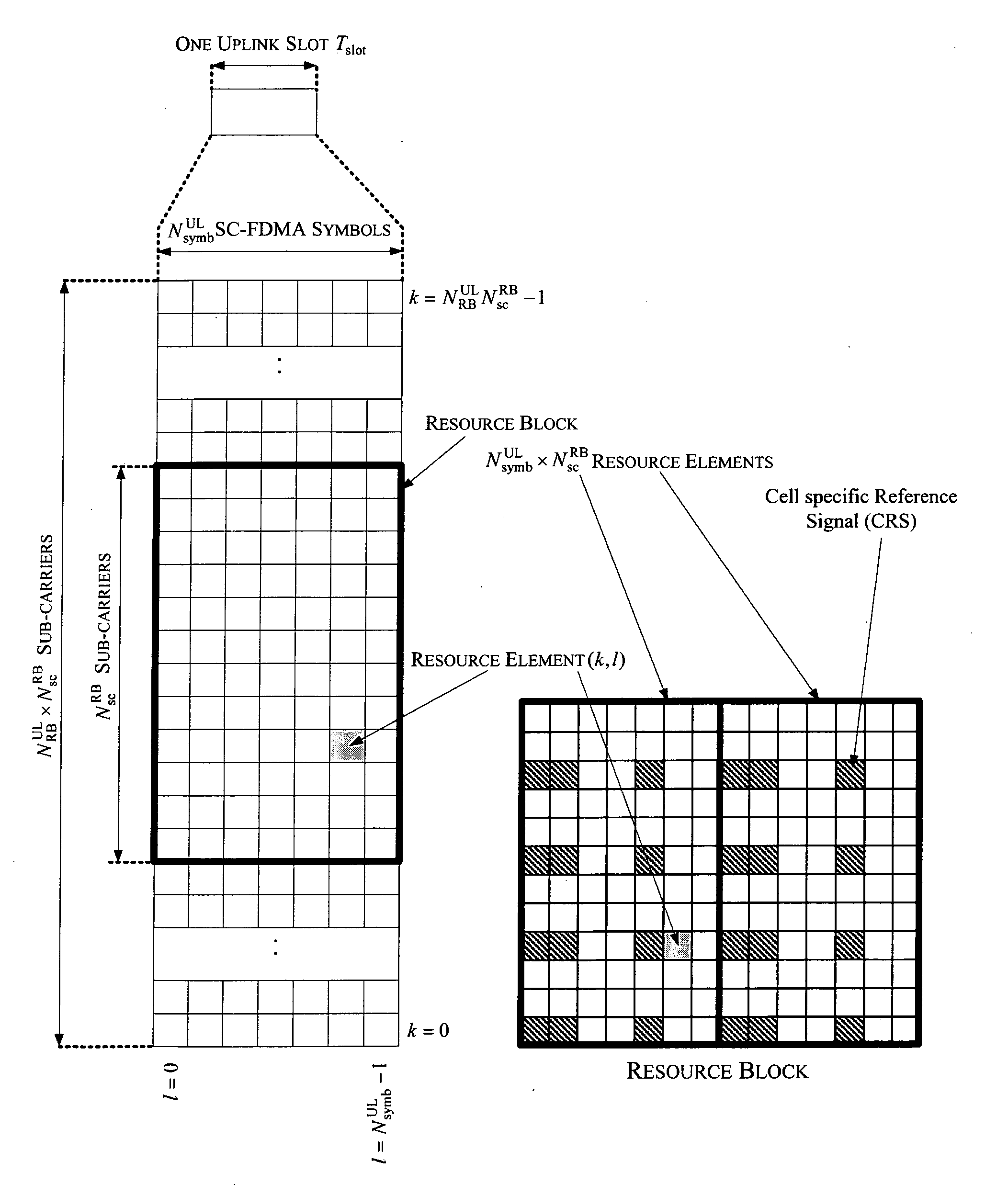
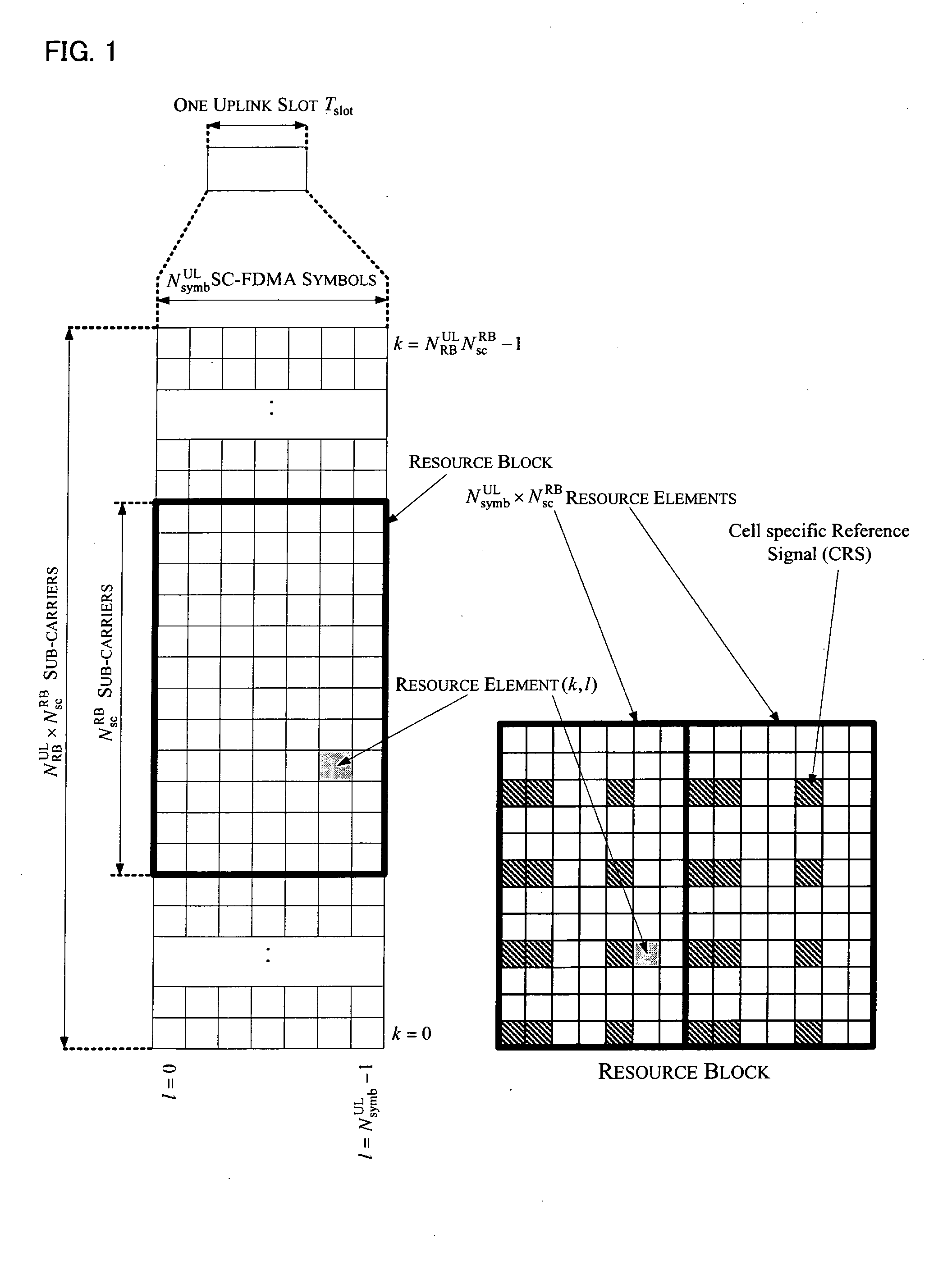
[0042]In an LTE system, a Cell-specific Reference Signal (CRS) is required for a user equipment (UE) to perform channel estimation and demodulation. The slot structure of the CRS is shown in FIG. 1 (see 3GPP 36....


PUM


Abstract

A method of notifying resource allocation for Demodulation Reference Signal (DMRS) is provided. A base station notifies to a user equipment a power offset value between an average EPRE value for data symbols and an average EPRE value for the DMRS at each layer in a semi-static or static manner. Also, the base station dynamically notifies to the user equipment a current channel rank or a current DMRS distribution pattern for the user equipment. The user equipment determines an allocated DMRS antenna port based on a correspondence between the received channel rank and an allocation of DMRS antenna port, thereby obtaining resource allocation information for the DMRS. The signaling overhead for power allocation in the system can be reduced, the efficiency of power amplifier can be improved and the flexibility of system scheduling can be increased. A method of notifying antenna port resource allocation for DMRS is also provided.

Description

TECHNICAL FIELD[0001]The present invention relates to a cellular mobile communication system, and more particularly, to a method for allocating downlink transmission power in a cellular communication system employing downlink beam-forming technique. Accordingly, a method of notifying resource allocation for Demodulation Reference Signal (DMRS) is provided.BACKGROUND ART[0002]In the conventional designs for LTE systems, downlink reception at a User Equipment (UE) is facilitated by channel estimation and symbol detection based on Cell specific Reference Signal (CRS). Since the CRS is a common reference signal, operations such as downlink data transmission power allocating and precoding at a base station (eNB) side need to be signaled to the UE such that the channel estimation and symbol demodulation can be performed at the UE side. However, this causes some inconvenience for multi-user MIMO scheduling and power allocation.[0003]In discussion of technical researches and standards for I...

Claims


Application Information

Patent Timeline
IPC IPC(8): H04W72/06H04W72/54
CPCH04L5/0023Y02B60/50H04B7/0426H04B7/0452H04B7/0465H04L5/0007H04L5/001H04L5/0016H04L5/0025H04L5/0044H04L5/0051H04L5/0092H04L5/0096H04L27/2613H04W52/143H04W52/22H04W52/225H04W52/228H04W52/42H04L5/0048H04L5/0091H04L5/0094H04L25/0224H04W52/325
Inventor ZHANG, YINGYULIU, RENMAODING, MINGLIANG, YONGMINGYANG, ZENG
Owner SHARP KK
Learn More