Wavelength diverse scintillation reduction

a scintillation reduction and wavelength technology, applied in the field of wavelength diverse scintillation reduction, can solve the problems of system distortion, image distorted generalization, and medium distortion, and achieve the effect of reducing the optical limitations of instruments and reducing the size of the optical field

Inactive Publication Date: 2012-08-16
TELEDYNE FLIR LLC
View PDF12 Cites 29 Cited by
  • Summary
  • Abstract
  • Description
  • Claims
  • Application Information

AI Technical Summary

Benefits of technology

[0004]Various methods have been developed to mitigate or eliminate the effects of image distortion. These methods generally rely on obtaining corrective information within the wavelength regime(s) in which imaging data are desired. For example, visible image data are used to correct visible images, and infrared image data are used to correct infrared images. However, calculating corrections using multispectral images has advantages that have not been previously exploited.

Problems solved by technology

Unfortunately, when an optical system obtains images based on image data that have passed through a medium, the images obtained generally will be distorted both by the medium and by the components of the optical system itself.
For example, the image of an object viewed with a telescope or other long-range imaging system may be distorted both by atmospheric effects (e.g., the scintillation, convection, turbulence, scatter, and varying index of refraction of the atmosphere, among others, which can induce various spatial and temporal perturbations in the incoming wavefront, etc.), and by mechanical, thermal, and optical limitations of the instrument (e.g., path-length error introduced by out-of-focus components of the field of view, limitations on the collection of spatial frequencies imposed by the objective aperture, uncorrected aberration in the objective lens, mirror deformations generated by supporting devices, etc.).
These distortions occur, for example, when ground-based telescopes (or other imaging instruments) obtain images of objects on the ground, in the air, or in space, and when airborne or space-based telescopes (or other imaging instruments) in aircraft or on satellites obtain images of objects within Earth's atmosphere, such as objects on or near Earth's surface.
The effects of atmospheric distortion can significantly limit image resolution.
For example, atmospheric distortion can limit the best “seeing conditions” to approximately one microradian at high-altitude astronomical observatories, looking straight up.
The limiting resolution becomes rapidly worse for lower-altitude and near-horizontal viewing scenarios typical for cameras and electro-optical systems.
The disadvantages associated with known image correction techniques may be particularly apparent when attempting to correct for scintillation.
Accordingly, existing algorithms used to correct for scintillation often result in significant delays in producing corrected images.
They also have the undesirable effect of blurring or smearing moving objects.
This is undesirable for any system mounted on a moving platform, such as an aircraft or ground vehicle, or for any other system in which viewing images in real time or near real time is important.

Method used


Image

  • Wavelength diverse scintillation reduction
  • Wavelength diverse scintillation reduction
  • Wavelength diverse scintillation reduction

Examples


example 1

Determination of Distortion Using Multiple Sensors

[0036]This example describes exemplary systems and methods for the direct determination of motion with multiple sensors; see FIGS. 1 and 2.

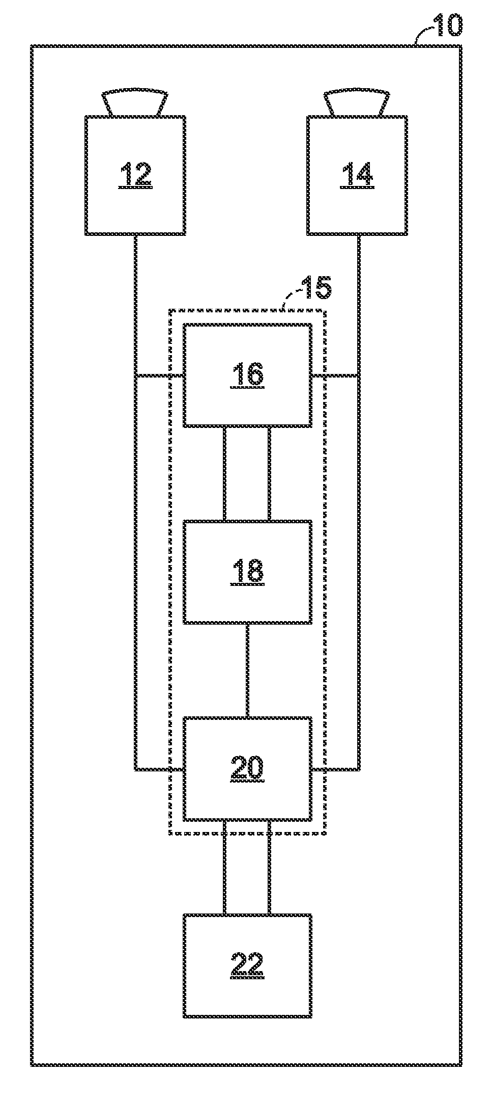
[0037]FIG. 1 depicts a first exemplary embodiment of an image correction system, generally indicated at 10, according to aspects of the present teachings. System 10 includes two sensors 12, 14, which are collectively capable of sensing image data in two separate wavelength regimes or wavebands. System 10 also includes a processor 15 that receives image data collected by sensors 12, 14 and performs an image correction function according to the present teachings. The process may include or employ first, second, and third processor functionalities 16, 18, 20, among other suitable configurations, for performing the image correction function. System 10 further may include a display and / or other output device 22 configured to display and / or otherwise make use of a corrected image, sequence of images, an...

example 2

Determination of Distortion Using a Single Sensor

[0060]This example describes exemplary systems and methods for the direct determination of motion with a single sensor; see FIGS. 3 and 4.

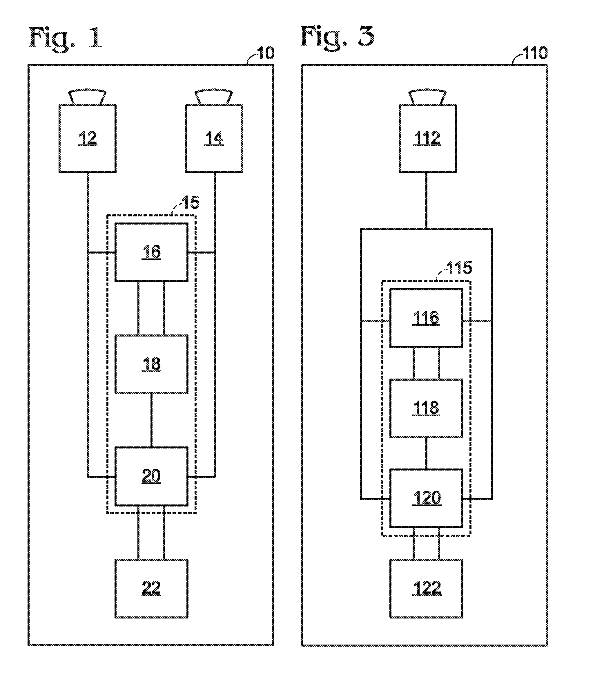
[0061]FIG. 3 depicts a second exemplary embodiment of an image correction system, generally indicated at 110, according to aspects of the present teachings. System 110 includes a single sensor 112, which is capable of sensing image data in a sufficient range of wavelengths so that the wavelength dependence of distortion-induced apparent motions may be observed and analyzed to a desired extent. System 110 further includes a processor 115, including a first processor functionality 116, a second processor functionality 118, and a third processor functionality 120. System 110 also may include a display and / or other output device 122 configured to display and / or otherwise make use of processed image data.

[0062]Sensor 112 may, for example, be a multispectral camera, such as a dual-band MWIR / LWIR camera wh...

example 3

Moving Support Platform

[0071]This example describes exemplary support platforms; see FIG. 5.

[0072]FIG. 5 depicts a helicopter 200 as an exemplary embodiment of a moving platform that might be used to support imaging systems according to the present teachings, and / or to practice methods of image correction according to the present teachings. Specifically, helicopter 200 includes a rotatable gimbal 202, within which may be disposed one or more sensors such as those described previously, including visible light and / or infrared sensors configured to collect light within various desired wavelength regimes. Also within gimbal 202, or otherwise mounted to helicopter 200, suitable processors may be disposed and configured to carry out the various image processing steps described above. Alternatively, one or more processors may be disposed at a remote location and configured to carry out some or all of the image processing steps contemplated by the present teachings. A display device such as...


PUM


Abstract

Systems, including apparatus and methods, for obtaining and / or correcting images, particularly from atmospheric and / or other distortions. These corrections may involve, among others, collecting two or more sets of image data corresponding to images of the same scene in different wavelength regimes, and using correlations between wavelength and expected distortion to distinguish apparent image motion due to distortion from apparent image motion due to object or scene motion. These systems may be useful in any suitable imaging context, including navigation, targeting, search and rescue, law enforcement, commercial video cameras and / or surveillance, among others.

Description

CROSS-REFERENCE TO RELATED APPLICATION [0001]This application is based upon and claims the benefit under 35 U.S.C. §119(e) of U.S. Provisional Patent Application Ser. No. 61 / 441,609, filed Feb. 10, 2011, which is incorporated herein by reference in its entirety for all purposes.INTRODUCTION [0002]Optical systems may be used to form and / or record images of objects and / or scenes. Unfortunately, when an optical system obtains images based on image data that have passed through a medium, the images obtained generally will be distorted both by the medium and by the components of the optical system itself. For example, the image of an object viewed with a telescope or other long-range imaging system may be distorted both by atmospheric effects (e.g., the scintillation, convection, turbulence, scatter, and varying index of refraction of the atmosphere, among others, which can induce various spatial and temporal perturbations in the incoming wavefront, etc.), and by mechanical, thermal, and...

Claims


Application Information

Patent Timeline
Patent Type & Authority Applications(United States)
IPC IPC(8): G06K9/40
CPCG02B27/0025G01J3/28G01J3/36G02B27/48G06K9/40G06T5/50G06T2207/20182G06T2207/30252G06T5/006
Inventor ARCHER, CYNTHIA I.
Owner TELEDYNE FLIR LLC
Why Eureka
Try Eureka