Flexible flat optical cable

a flexible, flat technology, applied in the direction of optics, fibre mechanical structures, instruments, etc., can solve the problems of optical fiber damage, and achieve the effect of preventing stress and increasing the bend radius

Inactive Publication Date: 2012-08-16
HITACHI METALS LTD
View PDF3 Cites 9 Cited by
  • Summary
  • Abstract
  • Description
  • Claims
  • Application Information

AI Technical Summary

Benefits of technology

[0008]It is an object of the invention to provide a highly reliable flexible flat optical cable that can prevent the damage of an optical fiber when being bent.(1) According to one embodiment of the invention, a flexible flat optical cable comprises:
[0027]According to one embodiment of the invention, a flexible flat optical cable is constructed such that a bend portion of an optical fiber core wire is located in a non-adhesive region of a base sheet, and the non-adhesive region allows the bend portion of the optical fiber core wire to move in a width direction of the base sheet. Thereby, the bend portion of the optical fiber core wire can be curved with a bend radius more than that in case of not allowing the bend portion of the optical fiber core wire to move in the width direction of the base sheet. Due to the increased bend radius, stress can be prevented from concentrating on one place of the optical fiber core wire so as to protect the optical fiber from being damaged at the bend portion of the optical fiber core wire.

Problems solved by technology

However, the flexible conductor disclosed in JP-A-563-228528 has a problem that, when it is bent to decrease a bend radius of the optical fiber at a bend portion, the optical fiber may be damaged.

Method used


Image

  • Flexible flat optical cable
  • Flexible flat optical cable
  • Flexible flat optical cable

Examples


first embodiment

[0049]A first embodiment of the invention will be described below in reference to the drawings.

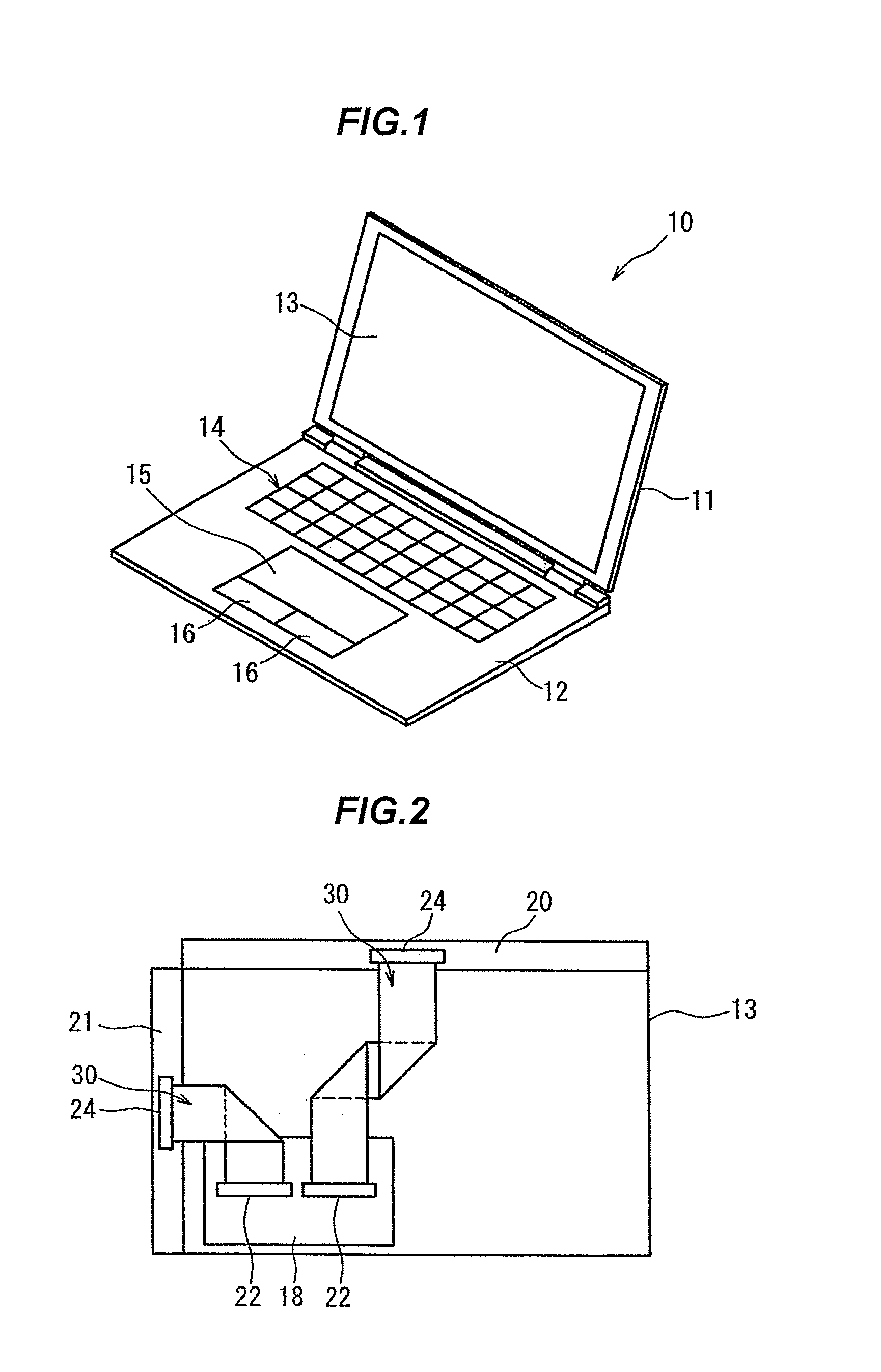
[0050]FIG. 1 is a schematic external perspective view showing a laptop computer 10 (notebook personal computer). The laptop computer 10 is, e.g., a fold-up computer in which a first case 11 is coupled to a second case 12 by a hinge. A liquid crystal panel 13 is installed on the first case 11 while a keyboard 14, a touchpad 15 and click buttons 16 are provided on the second case 12, and a user can obtain information from an image displayed on the liquid crystal panel 13.

[0051]FIG. 2 is a schematic plan view showing a back side of the liquid crystal panel 13 which is covered by the first case 11. A motherboard 18 is fixed to the back side of the liquid crystal panel 13.

[0052]An electrical component constituting a control circuit of the liquid crystal panel 13 is mounted on the motherboard 18 even though it is not illustrated. An arithmetic processing circuit and an image processing circuit, ...

second embodiment

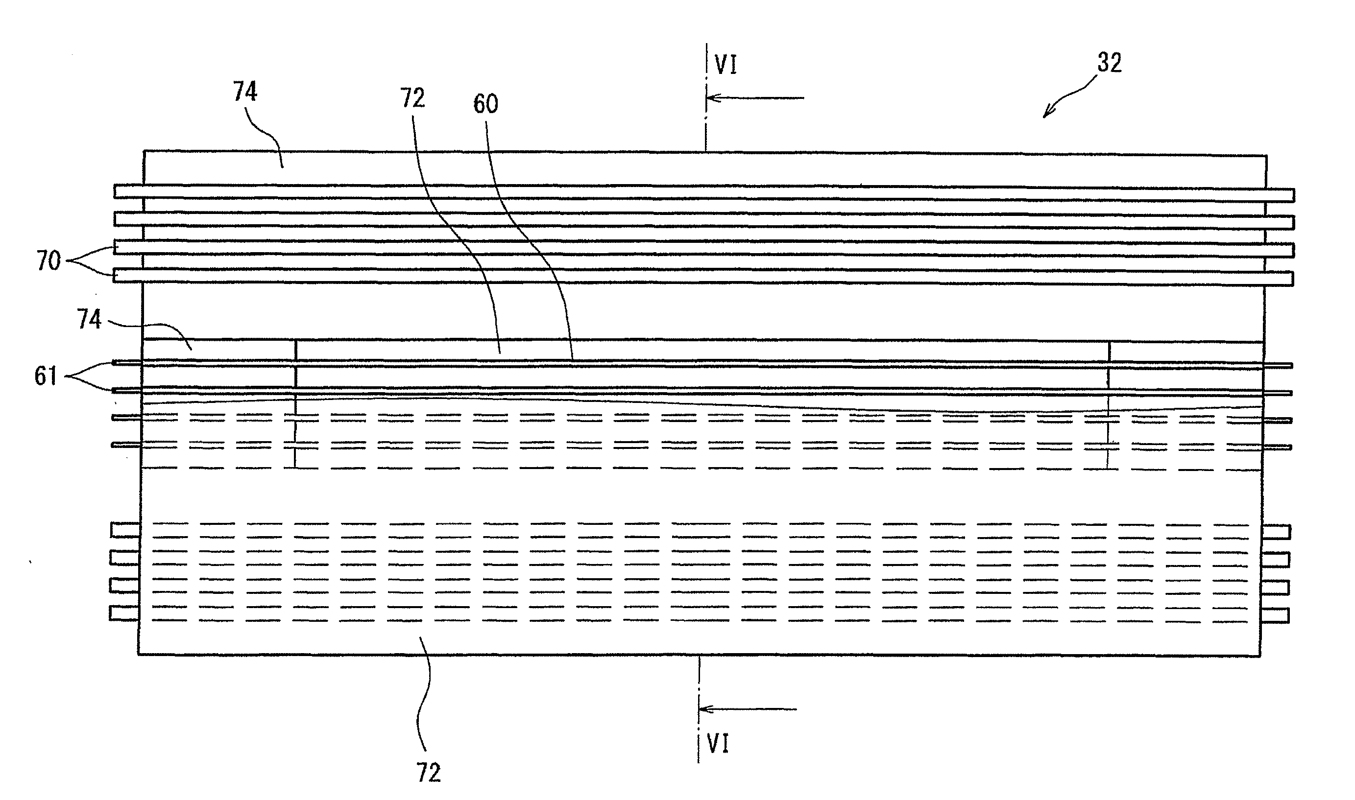
[0098]An FFOC 76 in a second embodiment will be described below. It should be noted that, in the following embodiments, the same constituent elements as those in the first embodiment are denoted by the same reference numerals and explanations thereof will be omitted.

[0099]FIG. 9 is a schematic cross sectional view showing the FFOC 76, which corresponds to FIG. 6. In the FFOC 76, an adhesive layer 78 is integrally formed on the entire inner surface of the base sheet 72. The adhesive layer 78 is formed of one selected from the group consisting of, e.g., acrylic, urethane and epoxy.

[0100]Then, a non-adhesive tape 80 is attached to a surface of the adhesive layer 78 opposite to the base sheet 72. The non-adhesive tape 80 has a length and a width which are sufficient to cover the middle portion of the plural optical fiber core wires 60.

[0101]The non-adhesive tape 80 is formed of one selected from the group consisting of, e.g., polyethylene terephthalate, polyester and polypropylene, and ...

third embodiment

[0106]An FFOC 82 in a third embodiment will be described below.

[0107]The FFOC 82 is different from the FFOC 76 in that a non-adhesive tape 84 is provided for each of the optical fiber core wires 60 as shown in FIG. 11.

[0108]For manufacturing the FFOC 82, plural non-adhesive tapes 84 are attached to the adhesive layer 78 as shown in FIGS. 12A and 12B.

[0109]Also in the FFOC 82 of the third embodiment, the non-adhesive region allows the bend portion 60a of the optical fiber core wire 60 to move in the width direction of the base sheet 72. This results in that damage to the optical fiber 61 at the bend portion 60a of the optical fiber core wire 60 is suppressed.


PUM


Abstract

A flexible flat optical cable includes two flexible base sheets, one or more optical fiber core wires arranged between the base sheets and each comprising at least an optical fiber, and an adhesive layer provided between the base sheets to bond the base sheets. A non-adhesive region is formed on a surface of the base sheets or the adhesive layer adjacent, in a thickness direction of the base sheets, to at least a portion of the optical fiber core wires for allowing a portion of the optical fiber core wires to move in a direction intersecting with an axial direction of the optical fiber core wires.

Description

[0001]The present application is based on Japanese Patent Application No. 2011-030763 filed on Feb. 16, 2011, the entire contents of which are incorporated herein by reference.BACKGROUND OF THE INVENTION[0002]1. Field of the Invention[0003]The invention relates to a flexible flat optical cable.[0004]2. Description of the Related Art[0005]In recent years, a flexible flat optical cable (hereinafter also referred to as “FFOC”) is used for wiring in various electronic devices.[0006]As an example of FFOC, JP-A-S63-228528 discloses a flexible conductor that an optical fiber is buried in an insulating support of a flexible printed circuit board.[0007]The FFOC needs to be positioned in electronic devices while being bent. However, the flexible conductor disclosed in JP-A-563-228528 has a problem that, when it is bent to decrease a bend radius of the optical fiber at a bend portion, the optical fiber may be damaged.SUMMARY OF THE INVENTION[0008]It is an object of the invention to provide a h...

Claims


Application Information

Patent Timeline
Patent Type & Authority Applications(United States)
IPC IPC(8): G02B6/44
CPCG02B6/43G02B6/4214
Inventor YU, JUHYUNHIRANO, KOUKIHIRUTA, AKIHIROOHKUBO, CHIHIRO
Owner HITACHI METALS LTD
Why Eureka
Try Eureka