Control device and control method of compressor

a control device and compressor technology, applied in the direction of pump control, positive displacement liquid engine, fluid engine, etc., can solve the problem of unstable phenomenon called “surge” in the compressor, and achieve the effect of saving adjustment effor

Inactive Publication Date: 2012-08-16
HITACHI LTD
View PDF8 Cites 27 Cited by
  • Summary
  • Abstract
  • Description
  • Claims
  • Application Information

AI Technical Summary

Benefits of technology

[0016]According to the invention, it is possible to provide a control device and control method of a compressor, which is capable of saving the effort of adjustment.

Problems solved by technology

However, when the flow rate becomes lower than a certain threshold, an unstable phenomenon called “surge” occurs in the compressor.

Method used


Image

  • Control device and control method of compressor
  • Control device and control method of compressor
  • Control device and control method of compressor

Examples


first embodiment

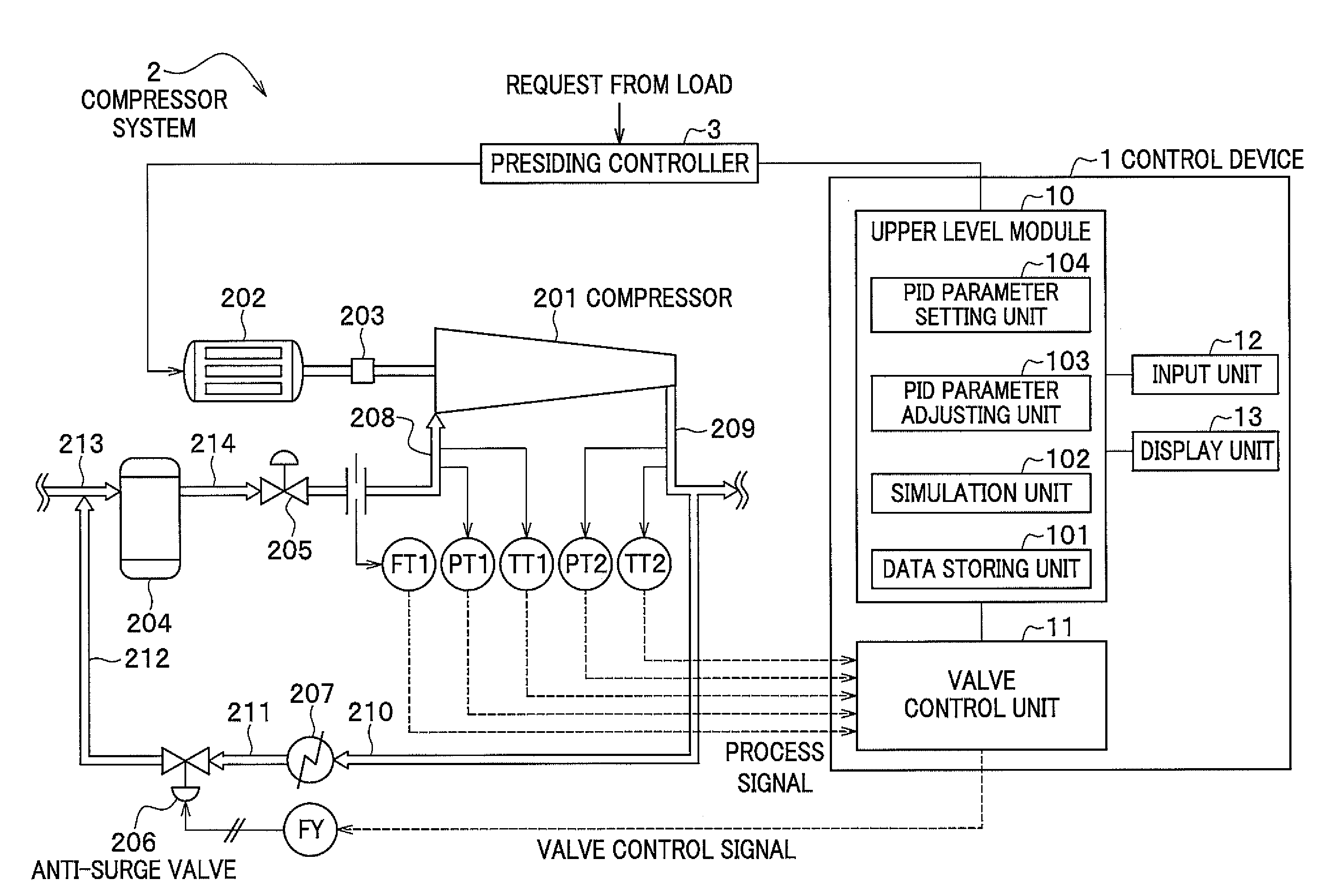
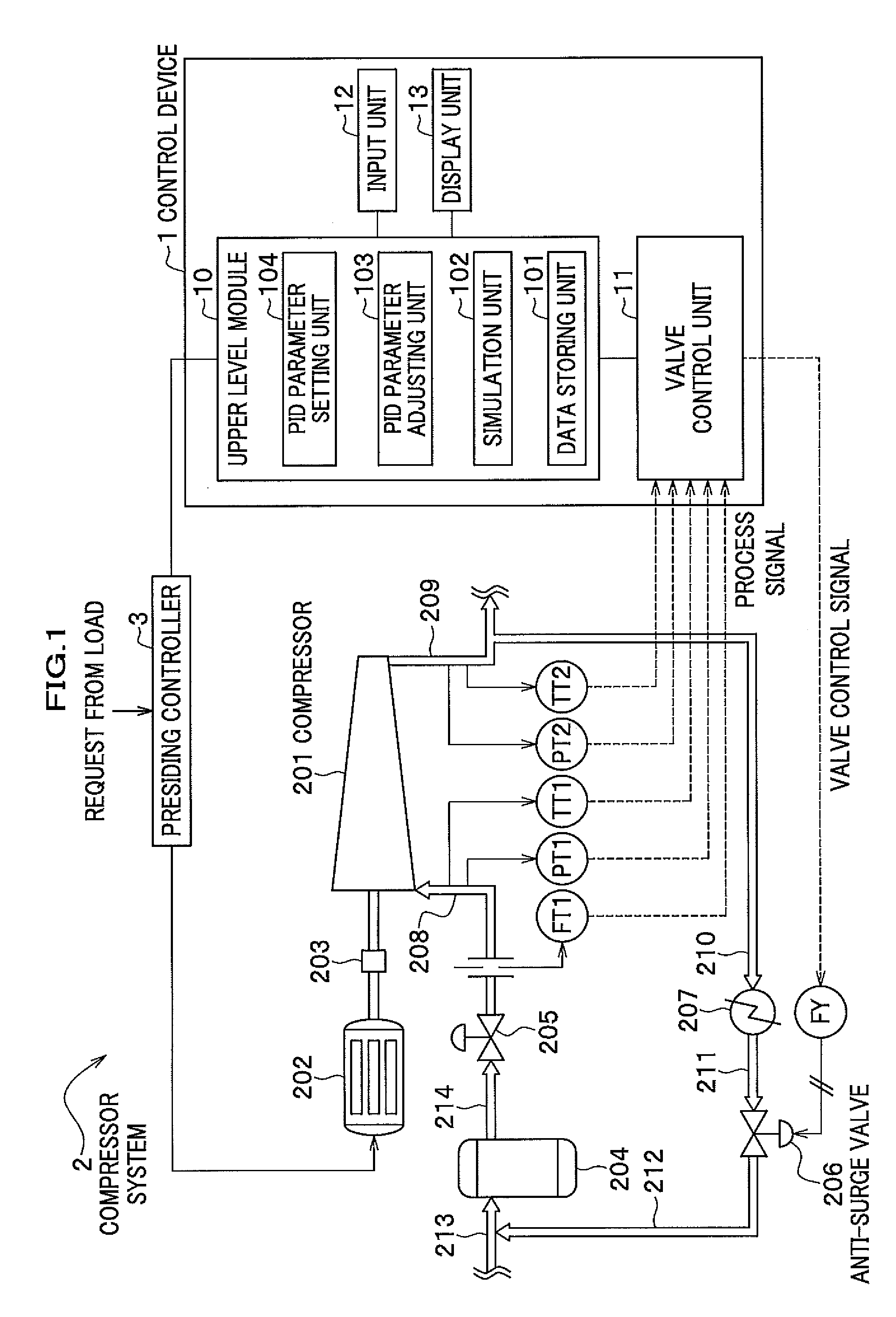
[0028]In a control device 1 according to the embodiment, as shown in FIG. 1, a simulation unit 102 of an upper level module 10 simulates operational status of a compressor 201 in a compressor system 2 on the basis of a plant model, and a PID parameter adjusting unit 103 adjusts a valve control parameter on the basis of the simulation result.

[0029]Here, the plant model represents a model that corresponds to each component of the actual compressor system 2 and the relations thereof, and the details of the plant model will be explained later.

Configuration of the Compressor System

[0030]First, will be explained a configuration of the control device 1 according to each embodiment of the present invention and the compressor system 2 that includes an anti-surge valve 206 which is to be controlled by the control device 1. FIG. 1 is a block diagram of the compressor system including the control device of the compressor according to the embodiment.

[0031]A single-axis multistage centrifugal com...

second embodiment

[0118]Next, will be explained a control device 1A of the compressor according to the second embodiment of the present invention.

[0119]The control device 1A according to the second embodiment performs model tuning on the basis of the valve control signal outputted by the valve control unit 11 so that the operating point (Qs′, hpol′) calculated by the upper level module 10A becomes closer to the actual operating point (Qs, hpol) of the compressor system 2.

[0120]FIG. 9 is a block diagram of a compressor system including a control device of a compressor according to the second embodiment of the invention. Comparing the control device 1A of this embodiment with that of the first embodiment, a model parameter adjusting unit 105 is added to the upper level module 10A. In addition, the simulation unit 102A is provided with an open-loop model Rm.

[0121]Meanwhile, since other components are same as those of the first embodiment, same symbols are used for the same components and the redundant e...


PUM


Abstract

A control device of a compressor includes a valve control unit configured to control an anti-surge valve that returns fluid in a discharge side of the compressor to a suction side of the compressor in accordance with a control parameter, a simulation unit configured to simulate operational status of the compressor in a plant in accordance with a plant model and the control parameter of the plant to which the compressor is installed, and a control parameter adjusting unit configured to adjust the control parameter in accordance with a result of the simulation.

Description

CROSS REFERENCE TO RELATED APPLICATIONS[0001]The present application claims benefit of the filing date of Japanese Patent Application No. 2011-027425 filed on Feb. 10, 2011, which is incorporated herein by reference.BACKGROUND OF THE INVENTION[0002]1. Field of the Invention[0003]The present invention relates to a control device and control method of a compressor.[0004]2. Description of the Related Art[0005]A process compressor (hereinafter called a “compressor”) is widely used for providing compressed gas in various types of plants such as plants in petrochemistry field. A compressor must be appropriately controlled to provide a stable discharge pressure or discharge flow rate required for a downstream process. However, when the flow rate becomes lower than a certain threshold, an unstable phenomenon called “surge” occurs in the compressor. Here, the surge means a vibration phenomenon that is accompanied by a pressure fluctuation or a backward flow in the compressor.[0006]In general...

Claims


Application Information

Patent Timeline
Patent Type & Authority Applications(United States)
IPC IPC(8): F04D27/02
CPCF04D27/0223F04D27/001
Inventor EBISAWA, NAOTOSUZUKI, KITAMIORIKASA, HIDEAKIHIWATARI, KEIICHIMIYANAGA, TAKESHI
Owner HITACHI LTD
Why Eureka
Try Eureka