Multi-axial pedicle fixation assembly and method for use

Active Publication Date: 2012-08-16
ORTHOFIX US LLC
View PDF19 Cites 39 Cited by
  • Summary
  • Abstract
  • Description
  • Claims
  • Application Information

AI Technical Summary

Benefits of technology

[0009]Also disclosed herein are various embodiments of a method of adjusting bone penetration depth of an implantable orthopedic assembly as described above. The method generally comprises fixating the bone fixator into bone, multi-axially repositioning the head assembly relative to the bone fixator until the desired position is achieved, and securing a stabilizing rod in a body component of the head assembly, such that further repositioning of the head assembly is prevented. Some embodiments may also comprise rotationally repositio

Problems solved by technology

Using implantable multi-axial pedicle fixation systems known in the art, surgeons may be challenged to obtain optimal bone purchase while obtaining optimal stabilizing rod position.

Method used


Image

  • Multi-axial pedicle fixation assembly and method for use
  • Multi-axial pedicle fixation assembly and method for use
  • Multi-axial pedicle fixation assembly and method for use

Examples


Embodiment Construction

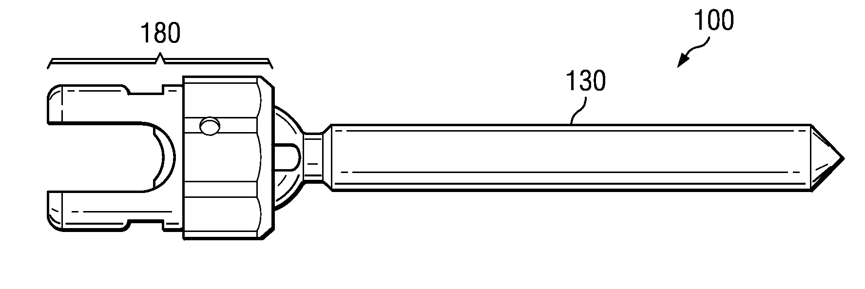
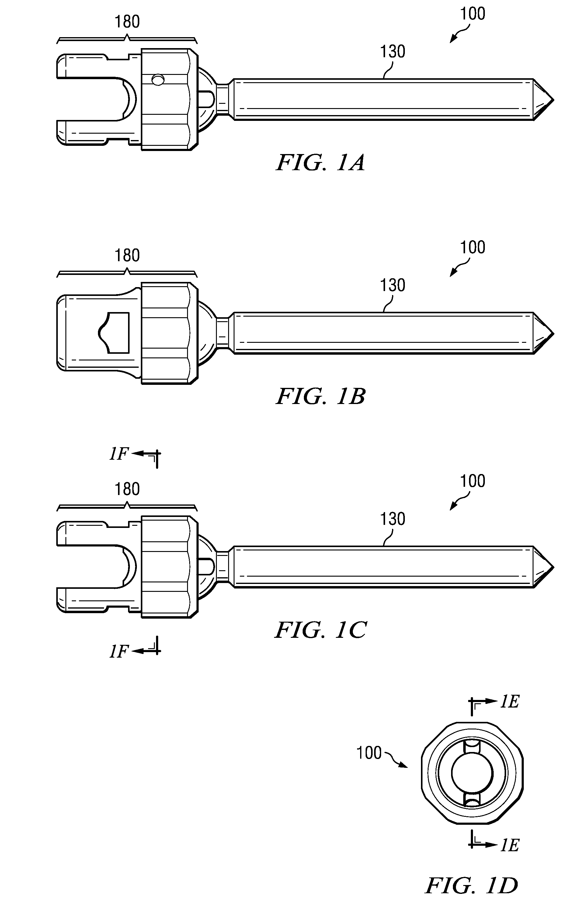
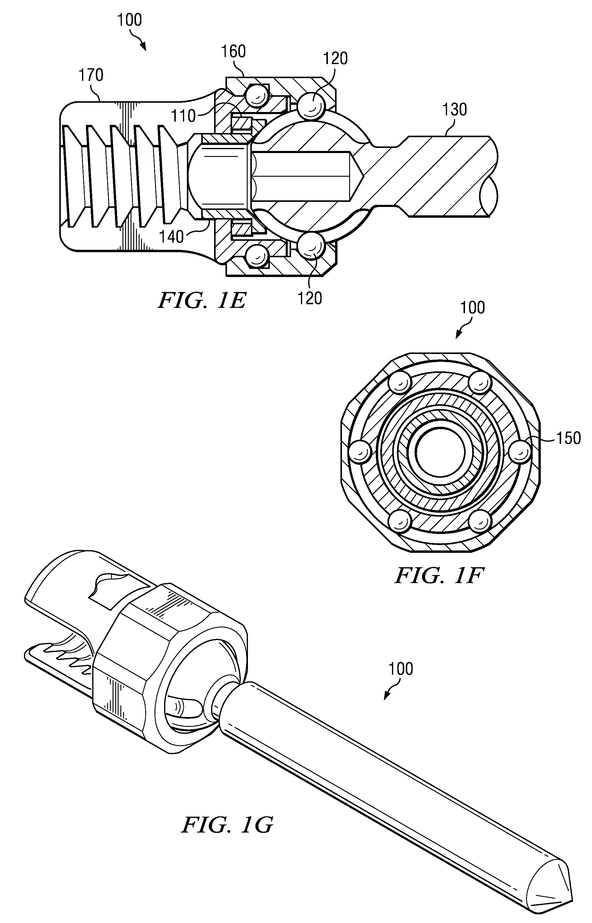
[0023]Various views of an exemplary embodiment of an implantable multi-axial pedicle fixation assembly 100 are illustrated in FIGS. 1A through 1G. Bone fixator 130 is angulatably connected to head assembly 180 such that the axis of bone fixator 130 may pivot relative to the axis of head assembly 180. Among other desirable benefits, this multi-axial feature maximizes range of motion and minimizes the need for extensive contouring of a spine stabilizing rod secured by head assembly 180, and also provides for simplified customization to accommodate variations in patient anatomy as well as variations in desired therapeutic benefits.

[0024]When the axis of bone fixator 130 and the axis of head assembly 180 are relatively aligned, such as during initial implantation, a primary drive interface may be used to adjust the depth at which bone fixator 130 penetrates the bone. The primary drive interface is located on bone fixator 130 and may be accessed with a tool inserted through head assembly...


PUM


Abstract

An implantable orthopedic assembly comprises a bone fixator and head assembly for securing a stabilizing rod to the spine. The head assembly allows multi-axial repositioning of the bone fixator relative to the head assembly. A primary drive interface located on the bone fixator may be used to adjust the depth of bone penetration when the bone fixator and head assembly are substantially coaxial. A secondary drive interface located on the head assembly may be used to adjust the depth of bone penetration while independently adjusting the stabilizing rod position when the bone fixator and the head assembly are not coaxial, transferring torsional loads to the bone fixator.

Description

TECHNICAL FIELD[0001]The disclosed embodiments relate generally to orthopedic implantable device technology, and more specifically to implantable devices for use in stabilizing the spine, including devices that penetrate the vertebral pedicle, lateral mass, or transverse process.BACKGROUND[0002]Spinal fixation devices may be surgically implanted in the body to effect a desired relationship between adjacent vertebral bodies. Such devices typically include a rigid stabilizing rod coupled to one or more devices for anchoring the rod to the vertebral bodies. The stabilizing rod must be contoured to accommodate variations in patient anatomy as well as variations in desired therapeutic benefits. Since each vertebral body varies in size and shape, a variety of anchoring devices have been developed. Pedicle screws have a shape and size appropriate for engaging pedicle bone. Using implantable multi-axial pedicle fixation systems known in the art, surgeons may be challenged to obtain optimal ...

Claims


Application Information

Patent Timeline
IPC IPC(8): A61B17/84
CPCA61B17/7037
Inventor TERMYNA, STEPHENLOVELL, JOHN
Owner ORTHOFIX US LLC
Why Eureka
Try Eureka