
Skeet Thrower

a thrower and hand-held technology, applied in the field of hand-held clay target throwers, can solve the problems of increasing the cost affecting the accuracy of clay target shooting, etc., and achieves the effect of improving the hand-held clay target thrower system and being readily adaptabl

Active Publication Date: 2012-08-23
GOOD SPORTSMAN MARKETING LLC
View PDF3 Cites 8 Cited by
  • Summary
  • Abstract
  • Description
  • Claims
  • Application Information

AI Technical Summary

Benefits of technology

"The present invention is a clay target thrower that improves upon conventional hand-held clay target throwers by providing a more efficient, comfortable, and weather-resistant device. The invention includes a flexible wire headend and a specially formed handle with a self-cocking block and impact backstop structure. The flexible wire headend is designed to securely hold and launch clay targets with ease. The invention allows for easy and fast loading and shooting of clay targets without additional assistance. The flexible wire headend is attached to the handle using an attachment point bend, which allows for a limited rotation range of about 135 degrees between the impact backstop structure and the self-cocking block component. The flexible wire headend occupies a first and second horizontal plane, providing at least two points of contact with the top and bottom surfaces of a loaded clay target to securely hold it in place prior to launch. The invention is designed to improve the art of manual clay target throwing."

Problems solved by technology

Many hand-held clay target throwers comprise multiple components, including a front-loading headend, a spring actuated launch mechanism, a handle, and other constituents which needlessly complicate manufacture and use of the devices.
Accordingly, the prior art provides several examples of sub-optimal hand-held clay target throwers which, among other things: require too many components which frustrate their manufacture and use; eliminate inclusion of a pivot point which results in a loss of beneficial momentum to the clay target upon launch; require loading techniques that disrupt the smooth operation and function of the device and / or promote clay target or clay pigeon breakage, thus, increasing the cost of clay target shooting and decreasing user enjoyment; failing to produce variable flight patterns; and that make their productive and recreational use unnecessarily difficult by not including reliable or consistent self-cocking block and release or launch mechanisms.

Method used


Image

  • Skeet Thrower
  • Skeet Thrower
  • Skeet Thrower

Examples


Embodiment Construction

[0065]Although the disclosure hereof is detailed and exact to enable those skilled in the art to practice the invention, the physical embodiments herein disclosed merely exemplify the invention which may be embodied in other specific structures.

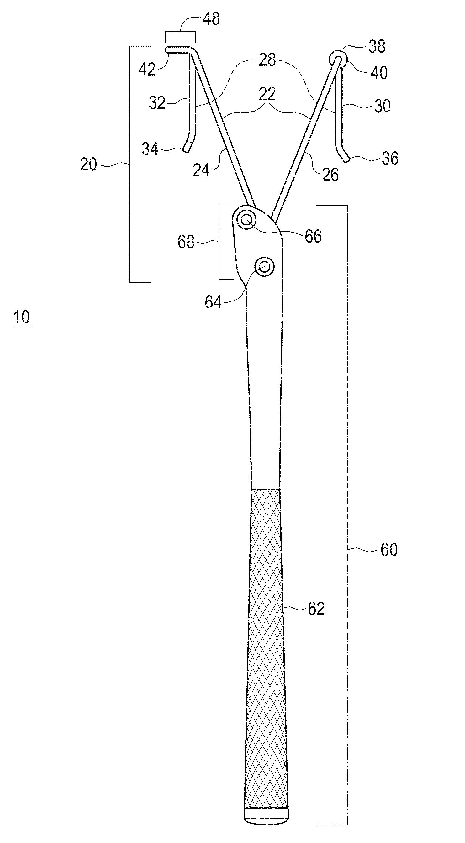
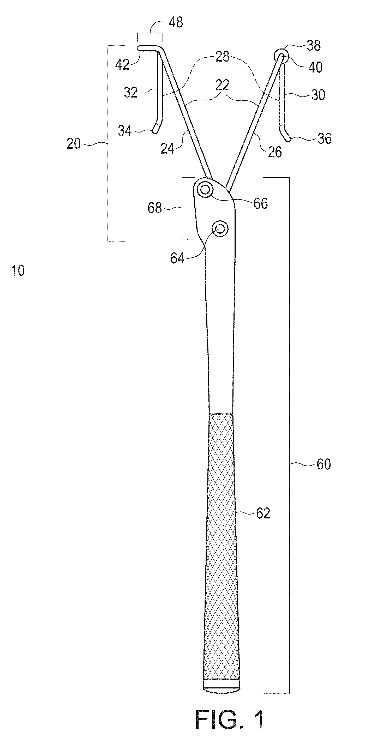
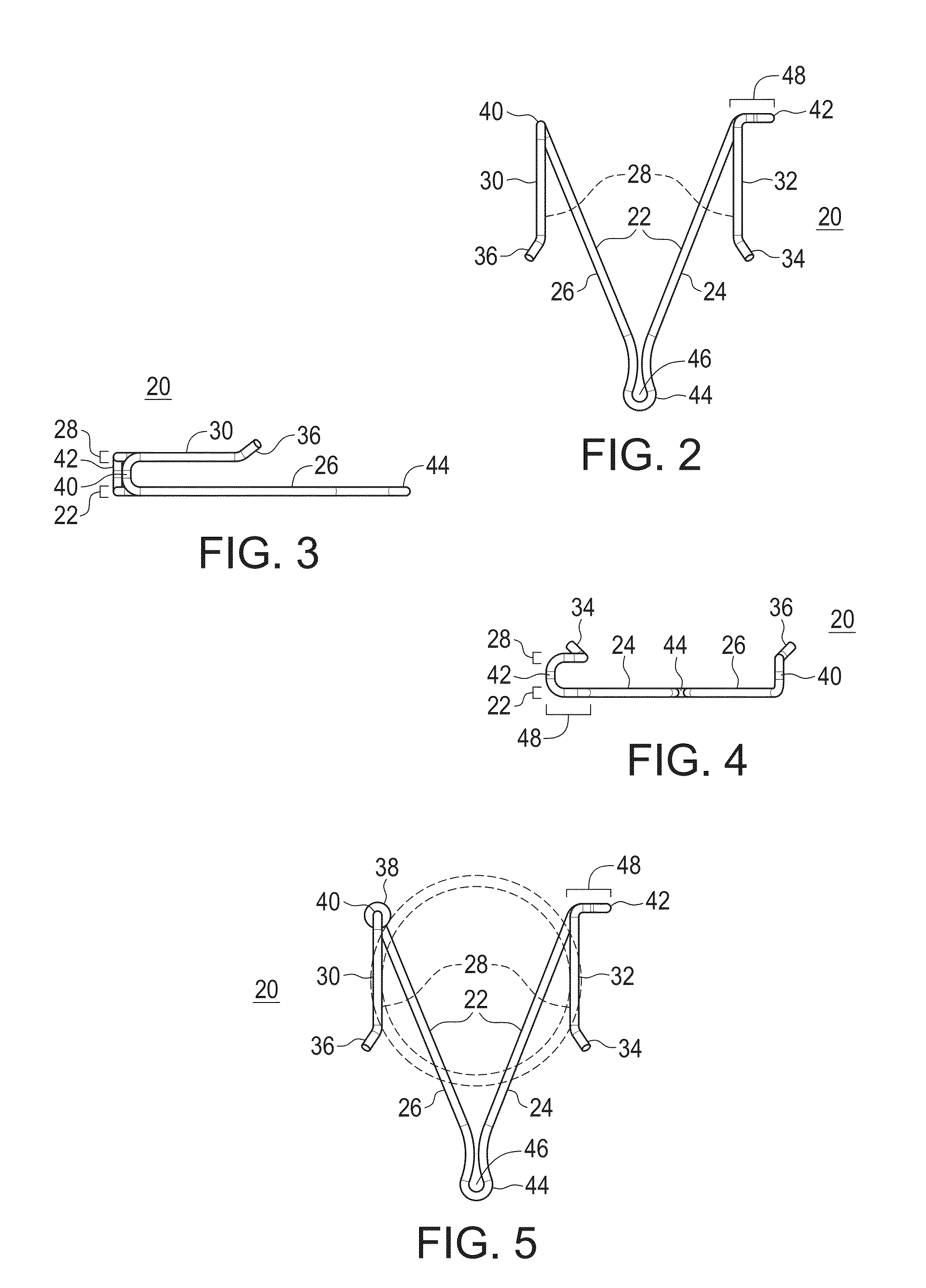
[0066]FIG. 1 provides a bottom elevation view of a clay target thrower 10 according to the present invention. Clay target thrower 10 generally comprises a flexible wire headend 20 and a handle 60. As depicted, flexible wire headend 20 includes a first (upper) horizontal plane 28 and a second (lower) horizontal plane 22. The support wire lengths 24 and 26 of the second horizontal plane 22 provide contact points to support the loaded clay target. Loading wire lengths 30 and 32 of the first horizontal plane 28 provide contact points to hold the loaded clay target at the shoulder. Loading bend extensions 34 and 36 tilt upward and vertically away from both the first (upper) and second (lower) horizontal planes at an angle of about 35 degrees and a...


PUM


Abstract

The present invention addresses problems not resolved by conventional hand-held clay target throwers by providing a clay target throwing device comprising two unique main components that, both separately and upon combination, provide for a significantly improved hand-held clay target thrower device. The first main component is a unitary rear-loading flexible wire headend. The second main component is a specially formed handle including a self-cocking block component and an impact backstop structure. Together the combined flexible wire headend and handle provide an easy-to-use, efficient, effective, comfortable, and weather-resistant hand-held self-cocking and controlled release clay target throwing unit.

Description

RELATED APPLICATIONS[0001]This application claims priority under 35 U.S.C. §119(e) to co-pending U.S. Provisional Patent Application Ser. No. 61 / 463,764, filed 23 Feb. 2011.BACKGROUND OF THE INVENTION[0002]1. Field of the Invention[0003]The present invention relates to the field of hand-held clay target throwers and, specifically, to a clay target thrower comprising two main components that are each unique unto themselves and that both separately and upon combination, provide for a significantly improved hand-held clay target thrower system. The first main component is a unitary rear-loading flexible wire headend. The second component is a specially formed handle including a self-cocking block component and an impact structure to assist the comfortable, efficient, and effective throwing and launch of a clay target.[0004]2. Description of Related Art[0005]Hand-held clay target throwers have been in use for well over a century, such that the prior art illustrates an on-going interest ...

Claims


Application Information

Patent Timeline
Patent Type & Authority Applications(United States)
IPC IPC(8): F41J9/28
CPCF41J9/28A63B65/10A63B59/30A63B60/0081
Inventor BLACK, THOMAS D.BLACK, GERALD B.
Owner GOOD SPORTSMAN MARKETING LLC
Learn More