Adjusting mechanism for adjusting rotary angle and antenna system therewith

a technology of adjusting mechanism and rotary angle, which is applied in the direction of machine supports, building scaffolds, other domestic objects, etc., can solve the problems of manufacturing cost, complicated assembly, and expensive cost of conventional adjusting mechanism, and achieve the effect of minimizing the volume of the adjusting mechanism, reducing the cost of assembly, and improving the connection

Active Publication Date: 2012-08-23
WISTRON NEWEB
View PDF34 Cites 24 Cited by
  • Summary
  • Abstract
  • Description
  • Claims
  • Application Information

AI Technical Summary

Benefits of technology

[0017]The bracket of the adjusting mechanism of the present invention includes the base and the four supporting portions. The four supporting portions are respectively disposed on four lateral sides of the base, which means the bracket can be a U-shaped structure, and the U-shaped structure can be connected to the lateral surface of the clamp via the bridging component for minimizing the volume of the adjusting mechanism. It should be mentioned that the structure of the bracket is not limited to the U-shaped structure of the above-mentioned embodiment. For example, the bracket can be a square structure or a polygon structure. The present invention improves connection between the bracket and the clamp, so that the angle of the antenna module relative to the supporting tube (the elevation and the azimuth) can be adjusted as the volume of the adjusting mechanism is minimized. Therefore, the adjusting mechanism of the present invention has advantages of easy assembly and easy operation, and manufacturing cost and transportation cost of the adjusting mechanism are decreased effectively.

Problems solved by technology

However, volume of the conventional adjusting mechanism is huge, so that the conventional adjusting mechanism has drawbacks of expensive cost and complicated assembly.
Thus, design of an adjusting mechanism of simple structure having low transportation cost and low manufacturing cost is an important issue of the antenna industry.

Method used


Image

  • Adjusting mechanism for adjusting rotary angle and antenna system therewith
  • Adjusting mechanism for adjusting rotary angle and antenna system therewith
  • Adjusting mechanism for adjusting rotary angle and antenna system therewith

Examples


Embodiment Construction

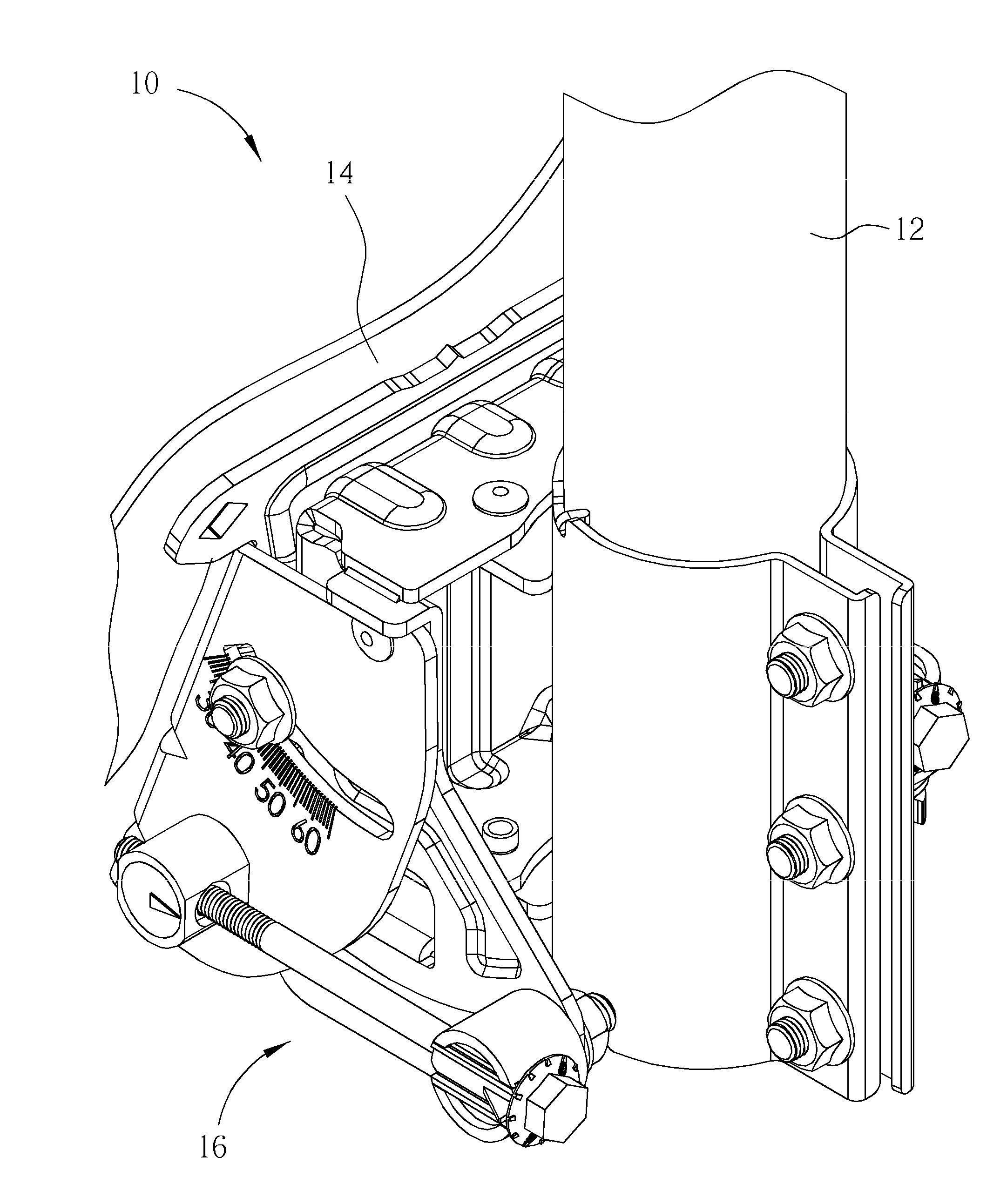
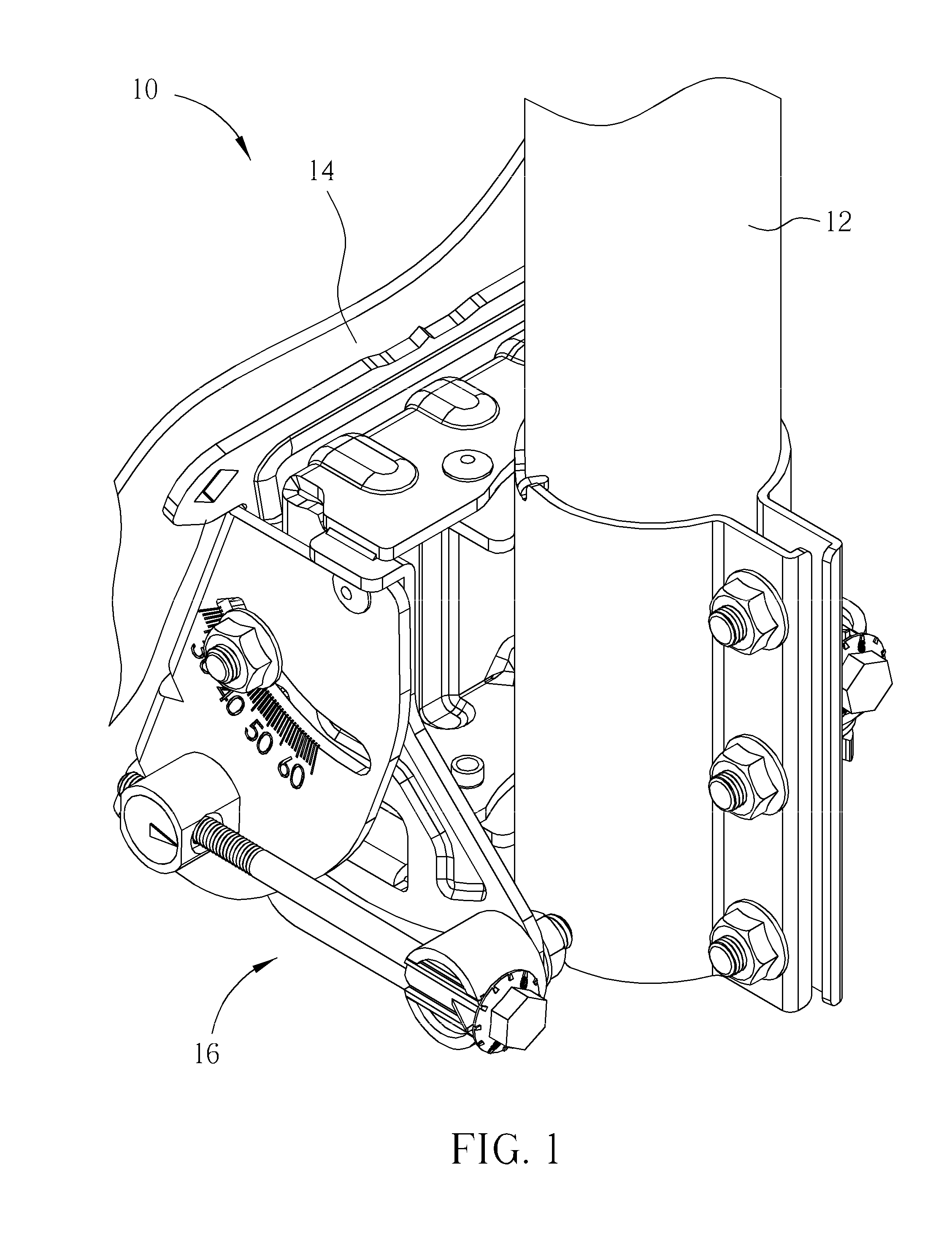
[0021]Please refer to FIG. 1 and FIG. 2. FIG. 1 and FIG. 2 are diagrams of an antenna system 10 in different view angles according to an embodiment of the present invention. The antenna system 10 includes a supporting tube 12, an antenna module 14 and an adjusting mechanism 16. The adjusting mechanism 16 is installed on the supporting tube 12 and connected to the antenna module 14, so as to adjust an angle of the antenna module 14 relative to the supporting tube 12 for directionally aligning toward a satellite. In this embodiment, the adjusting mechanism 16 is for adjusting an azimuth and an elevation of the antenna module 14 relative to the supporting tube 12 and the satellite.

[0022]Please refer to FIG. 3 to FIG. 5. FIG. 3 to FIG. 5 are exploded diagrams of the adjusting mechanism 16 in different view angles according to the embodiment of the present invention. The adjusting mechanism 16 includes a bracket 18. The bracket 18 includes a base 20, a first supporting portion 22 dispose...


PUM


Abstract

An adjusting mechanism for adjusting rotary angle is disclosed in the present invention. The adjusting mechanism includes a bracket. The bracket includes a base, a first supporting portion disposed on a first lateral side of the base, and a second supporting portion disposed on a second lateral side of the base. A pivot hole is formed on the first supporting portion. The adjusting mechanism further includes a clamp disposed by a side of the base and located in a position corresponding to the first and the second supporting portion. The adjusting mechanism further includes at least one bridging component connecting to a lateral surface of the clamp, and a pivoting component. A pivot hole is formed on the bridging component. The pivoting component passes through the pivot holes on the first supporting portion and the bridging component, so as to pivot the first supporting portion relative to the bridging component.

Description

BACKGROUND OF THE INVENTION[0001]1. Field of the Invention[0002]The present invention relates to an adjusting mechanism for adjusting rotary angle, and more particularly, to an adjusting mechanism for adjusting rotary angle of an antenna module and a related antenna system.[0003]2. Description of the Prior Art[0004]For receiving signals generated by a satellite effectively, an antenna module includes an adjusting mechanism for adjusting rotary angle of the antenna module according to a position of the satellite relative to the ground. A conventional adjusting mechanism for adjusting an elevation and an azimuth of the antenna module relative to the satellite includes a sheath and a rotating structure. The sheath sheathes on a supporting tube, and the rotating structure is disposed on an end of the sheath (for example, the rotating structure is disposed on top of the sheath), so that the conventional adjusting mechanism can adjust the elevation and the azimuth of the antenna module re...

Claims


Application Information

Patent Timeline
Patent Type & Authority Applications(United States)
IPC IPC(8): H01Q1/12F16M13/00
CPCH01Q1/1228H01Q3/02H01Q1/125
Inventor LIN, HUNG-YUANKUO, SAN-YIYANG, LAN-CHUNLEE, MING-CHANCHIEN, WEI-TE
Owner WISTRON NEWEB
Why Eureka
Try Eureka