Wind sensor system using blade signals

a sensor system and wind sensor technology, applied in the direction of engine control parameters, comparison table algorithms, engine fuctions, etc., can solve the problems of inability to individually estimate wind speed and wind direction without additional measurements or assumptions, and the claimed method does not provide the desired wind speed-velocity field quantities

Active Publication Date: 2012-08-23
NIDEC SSB WIND SYST GMBH
View PDF1 Cites 20 Cited by
  • Summary
  • Abstract
  • Description
  • Claims
  • Application Information

AI Technical Summary

Problems solved by technology

This correction is difficult to measure or quantify, as mentioned above.
However, the wind speed and wind direction cannot be individually estimated without additional measurements or assumptions.
Thus, the claimed method does not provide the desired wind-velocity field quantities, as described above.
While the aeroelastic equations of motion of a wind turbine, or a component thereof, can be written explicitly, the forces appearing within these equations often cannot be.
These states are not known or easily measured, due to the effects of turbulence both near and far from the the blades' surface, as well as the roughness condition of the blade's surface itself.
As mentioned above, the estimation of the induced velocity rests on knowledge of the instantaneous aerodynamic state of the rotor blades, which is difficult to measure.
Therefore, the subtraction of the rotor speed from the apparent speed makes the resulting quantity sensitive to noise and prone to excessive error.
Lastly, the outboard location of the sensors makes the sensors difficult to maintain, replace, or service, as well as prone to lightning strikes, dirt build-up, and other atmospheric effects.
More importantly, SODAR and LIDAR systems are too expensive for use in commercial wind turbines (i.e. beyond the prototype stage).

Method used


Image

  • Wind sensor system using blade signals
  • Wind sensor system using blade signals
  • Wind sensor system using blade signals

Examples


Embodiment Construction

[0016]The invention can be applied to a rotor with two or more blades, including rotors having three blades attached to the rotor through a pitch bearing.

[0017]Wind Velocity Field Characteristics

[0018]The wind velocity field characteristics used in this invention are wind velocity values spatially averaged over the rotor swept area. Since the average is in space only, the time variation of the data is not affected.

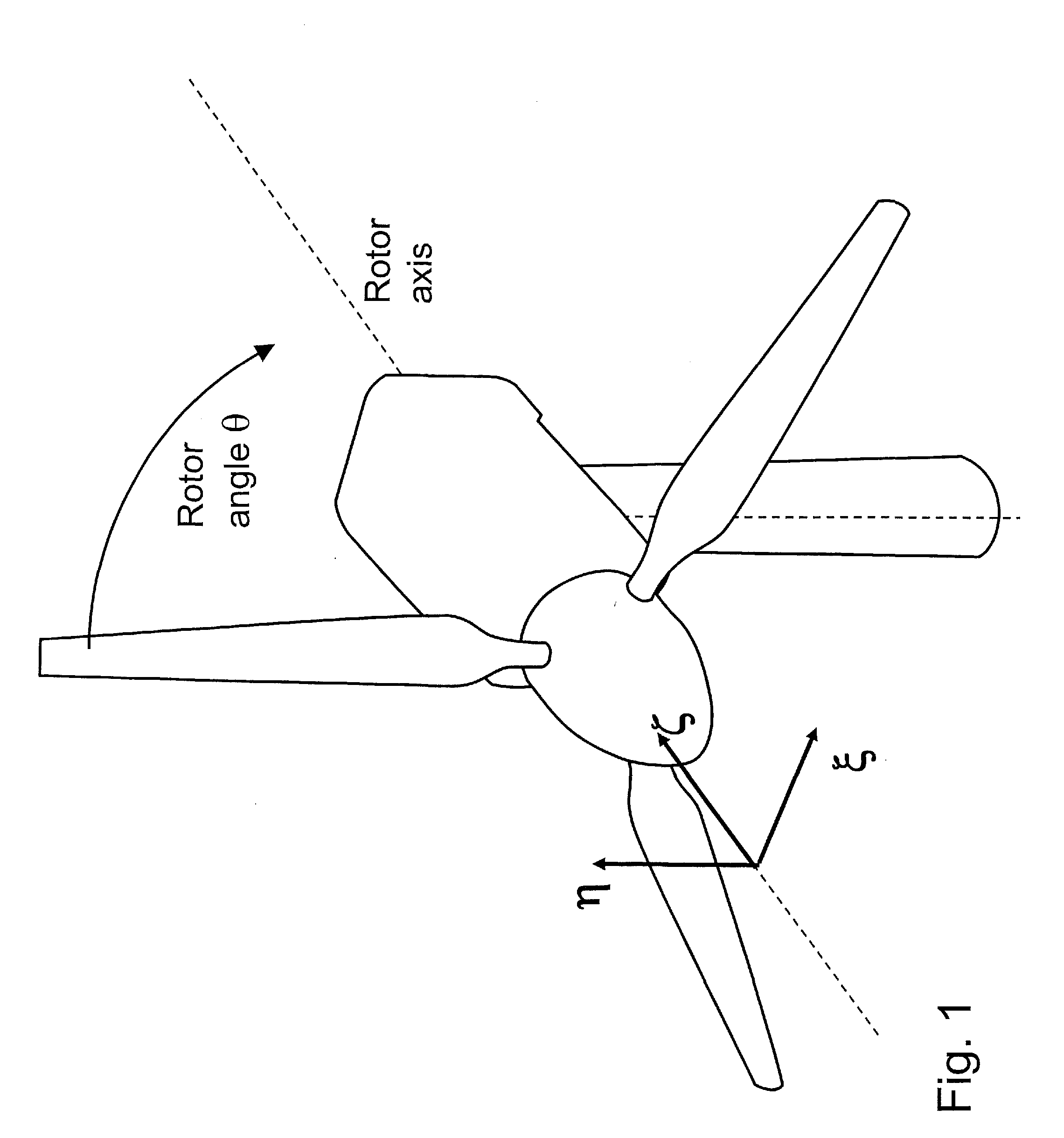
[0019]In the following description, use is made of a coordinate system, with coordinates ξ, η, ζ, that is non-rotating, hence fixed with the nacelle. See FIG. 1. The ζ coordinate is pointing along the axis of rotation of the rotor, denoted by the unit vector n. (Bold letters denotes vectors, as is customary in the art). The coordinate η points vertically up, and the axis ξ completes the orthogonal coordinate system by pointing in the horizontal direction.

[0020]A first wind velocity field characteristic is the mean wind velocity:

Vm(t)=1A∫∫V(t)A(1)

where A is the rotor swept ...


PUM


Abstract

The present invention relates to a wind-velocity-field measurement system for use in a wind turbine having a rotor with two or more blades, comprising at least one sensor-signal obtained by measuring a physical quantity on at angle least one of the blades, the physical quantity being indicative of at least one wind-velocity-field characteristic; a table (140, 142, 144) build for a plurality of wind conditions by associating values characterizing the at least one sensor-signal with values of the at least one wind-velocity-field characteristic, and; searching means (150, 152, 154) for determining from the table a value of the at least one wind-velocity-field characteristic for a current wind condition given values characterizing the at least one sensor-signal.

Description

PRIOR ART[0001]Modern wind turbine almost exclusively use blades that are pitchable about their longitudinal axis to regulate the blades' angle of attack, hence the blades' lift and drag forces. Collective pitch motion between all blades attached to the rotor is used for regulation of aerodynamic power extracted from the wind, while individual pitch control is mainly used to alleviate or reduce loads experienced by the blades during normal operation in non-steady wind conditions.[0002]For effective individual pitch control, essentially instantaneous knowledge of the wind velocity field over the rotor swept area is needed. Wind velocity field characteristics of particular importance are wind speed, wind direction, horizontal wind shear, and vertical wind shear. These characteristics are most suitable for control when they are spatially averaged over the rotor swept area, yet essentially all turbines commercially sold today use a single (spatial) point measurement provided by one wind...

Claims


Application Information

Patent Timeline
Patent Type & Authority Applications(United States)
IPC IPC(8): H02P9/02
CPCF03D7/042F03D11/0091F05B2240/221F05B2260/821Y02E10/723F05B2270/708F05B2270/802F05B2270/808Y02E10/722F05B2270/32F03D17/00Y02E10/72F05B2270/321
Inventor BERTOLOTTI, FABIOVAN SCHELVE, JENS
Owner NIDEC SSB WIND SYST GMBH
Why Eureka
Try Eureka