Uniform keyboard illumination

Inactive Publication Date: 2012-08-23
RES IN MOTION LTD
View PDF5 Cites 6 Cited by
  • Summary
  • Abstract
  • Description
  • Claims
  • Application Information

AI Technical Summary

Problems solved by technology

Since backlighting demands power, backlighting results in deple

Method used


Image

  • Uniform keyboard illumination
  • Uniform keyboard illumination
  • Uniform keyboard illumination

Examples


Embodiment Construction

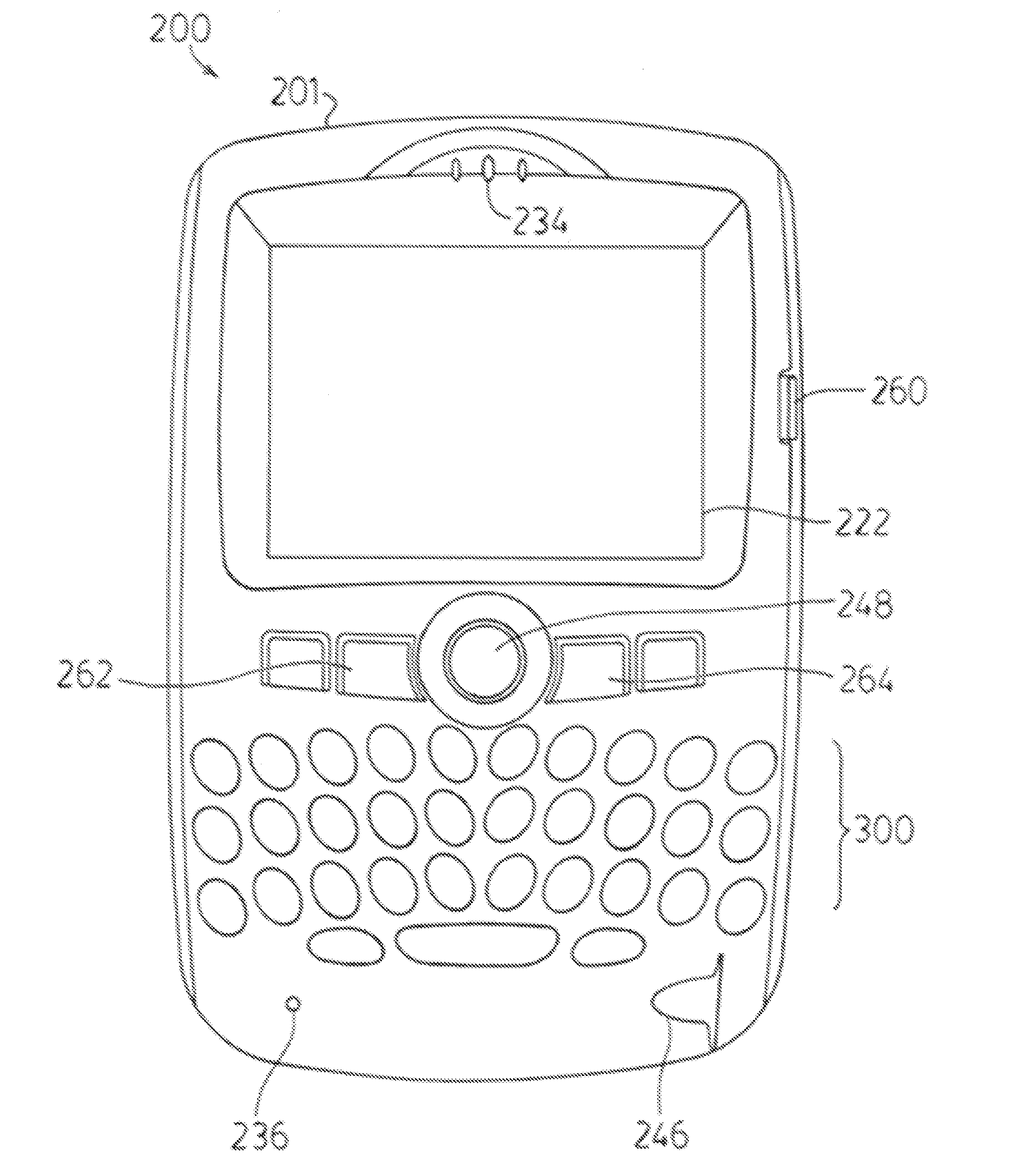
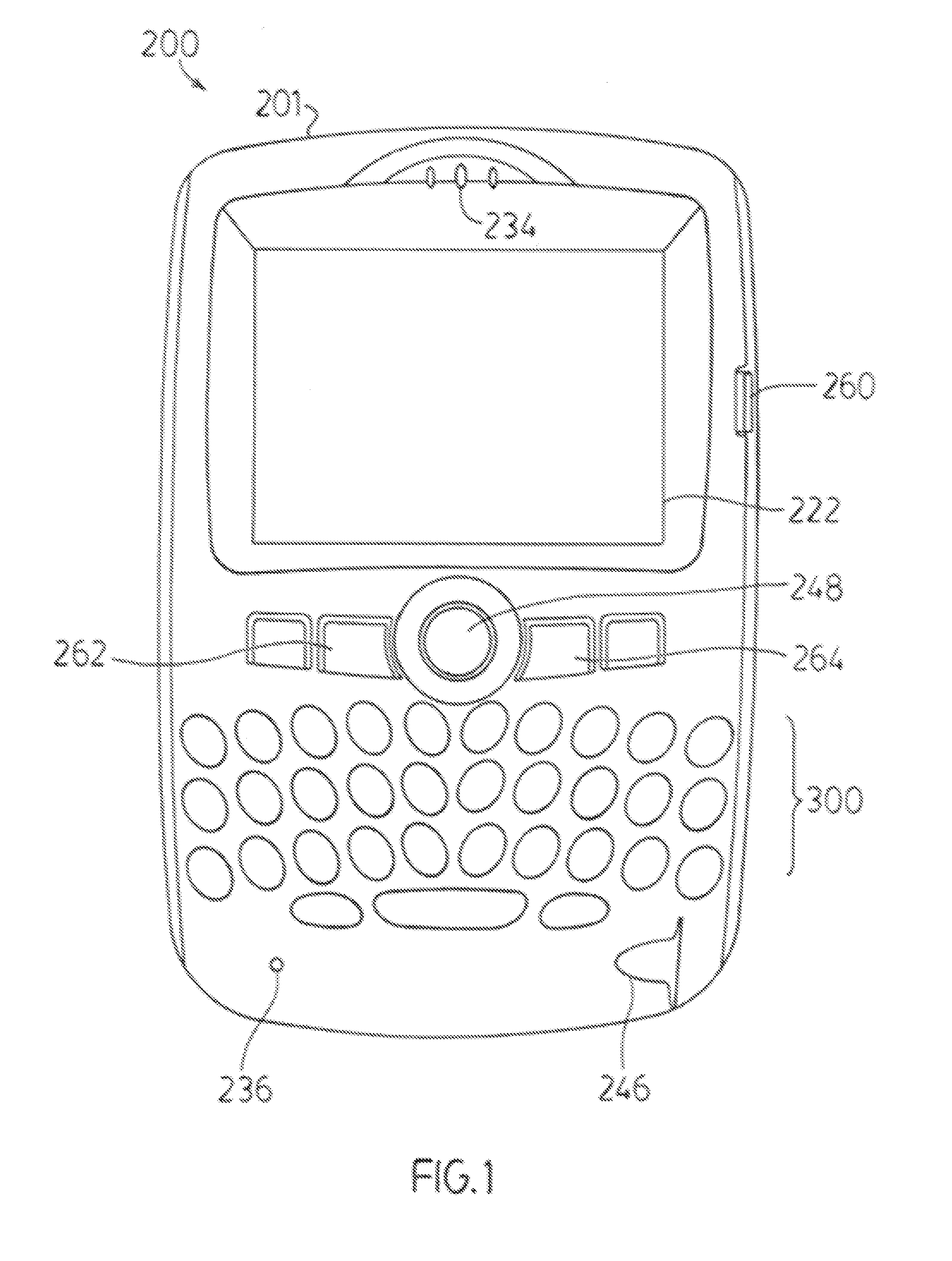
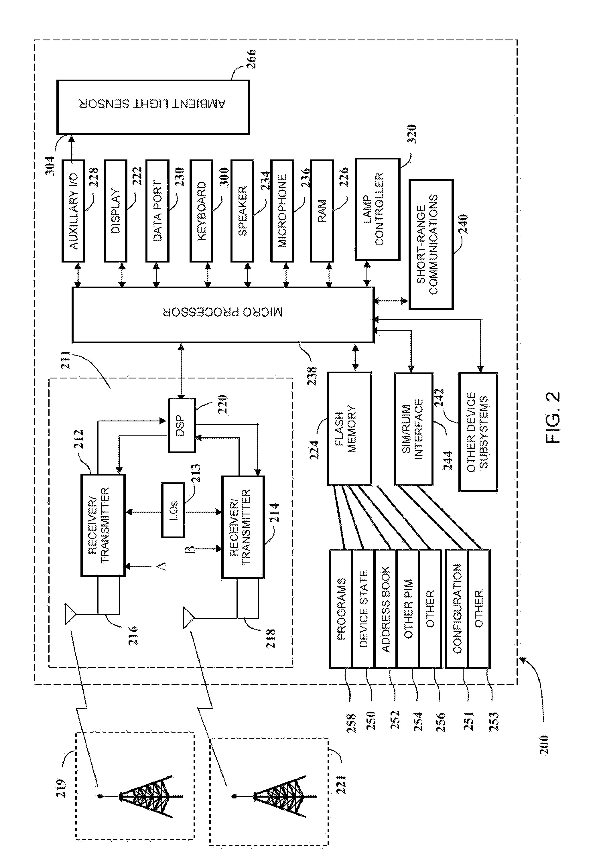
[0013]A typical keyboard or keypad backlight includes a flat light guide plate that is disposed below the array of keys, and a number of light emitting elements—such as light emitting diodes (LEDs)—that are scattered throughout the light guide. Alternately, the LEDs may be positioned along one of the side walls of the light guide plate.

[0014]Maintaining uniformity in the intensity of light produced by the backlight, across the keyboard / keypad can be difficult owing to variations in the characteristics of the LEDs. These deficiencies may be typically addressed by providing each LED with its own current source / sink, and matching the current sources / sinks. However, the large number of matched current sources / sinks and associated connections increases the size and cost of the power management integrated circuit. There may be other drawbacks to this arrangement as well.

[0015]In contrast to an approach that tries to match LEDs is an approach that tries to promote uniformity by manufacturi...


PUM


Abstract

An input device includes an array of keys and an illumination system. Each key comprises a key face that is configured for transmission of light. The illumination system includes a light guide disposed below the keys, a plurality of lamps mounted to the light guide, and a lamp controller electrically coupled to the lamps. The light guide is configured to illuminate the key faces via the lamps. The lamp controller is configured to repeatedly illuminate the lamps each for a respective on-time interval of a common illumination period. The location of the lamps and the illumination period and each said on-time interval are selected for the visual appearance of continuous substantially uniform illumination of the array of keys.

Description

FIELD OF THE INVENTION[0001]This patent application relates to a method of illuminating a data input device of an electronic communications device and, in particular, to a uniform keyboard / keypad illumination.BACKGROUND OF THE INVENTION[0002]Many portable electronic communications devices, such as wireless telephones, personal data assistants, and wireless pagers, include a data input device, such as a keyboard or keypad, for providing text input and / or controlling the device. The keyboard or keypad includes an array of keys, that is, a plurality of physical buttons or other actuators formed in a useful arrangement. To facilitate viewing of the input device in dim ambient light, the communications device may include a lamp, such as a keyboard / keypad backlight, that illuminates the keys of the input device when the communications device is active. Since backlighting demands power, backlighting results in depletion of the power stored in the device's portable power supply. Accordingly...

Claims


Application Information

Patent Timeline
IPC IPC(8): H03M11/02H01H13/76
CPCH01H13/83H01H2219/062G02B6/0081G02B6/0073G02B6/0068
Inventor BROGA, MATTHEWFLETCHER, BERGEN
Owner RES IN MOTION LTD
Why Eureka
Try Eureka