Method and apparatus for tile based depth buffer compression

a depth buffer and depth buffer technology, applied in the field of methods and apparatus for tile based depth buffer compression, can solve the problems of large number of memory accesses (reads and writes) to the depth buffer memory, large and fast memory subsystems are expensiv

Active Publication Date: 2012-08-23
IMAGINATION TECH LTD
View PDF14 Cites 20 Cited by
  • Summary
  • Abstract
  • Description
  • Claims
  • Application Information

AI Technical Summary

Problems solved by technology

A large number of polygon fragments are likely to be tested at each pixel position, leading to a very large number of memory accesses (reads and writes) to the depth buffer memory.
A large and fast memory subsystem is expensive, and so it is desirable to reduce the number of memory accesses wherever possible.

Method used

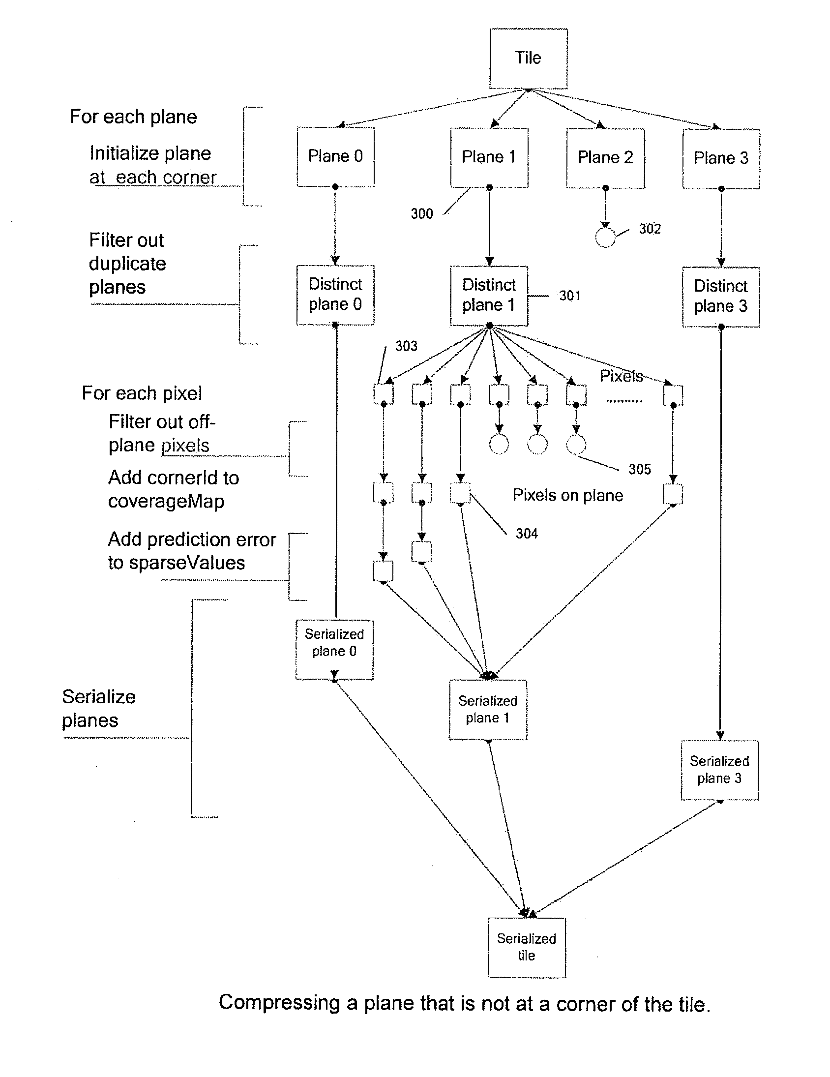
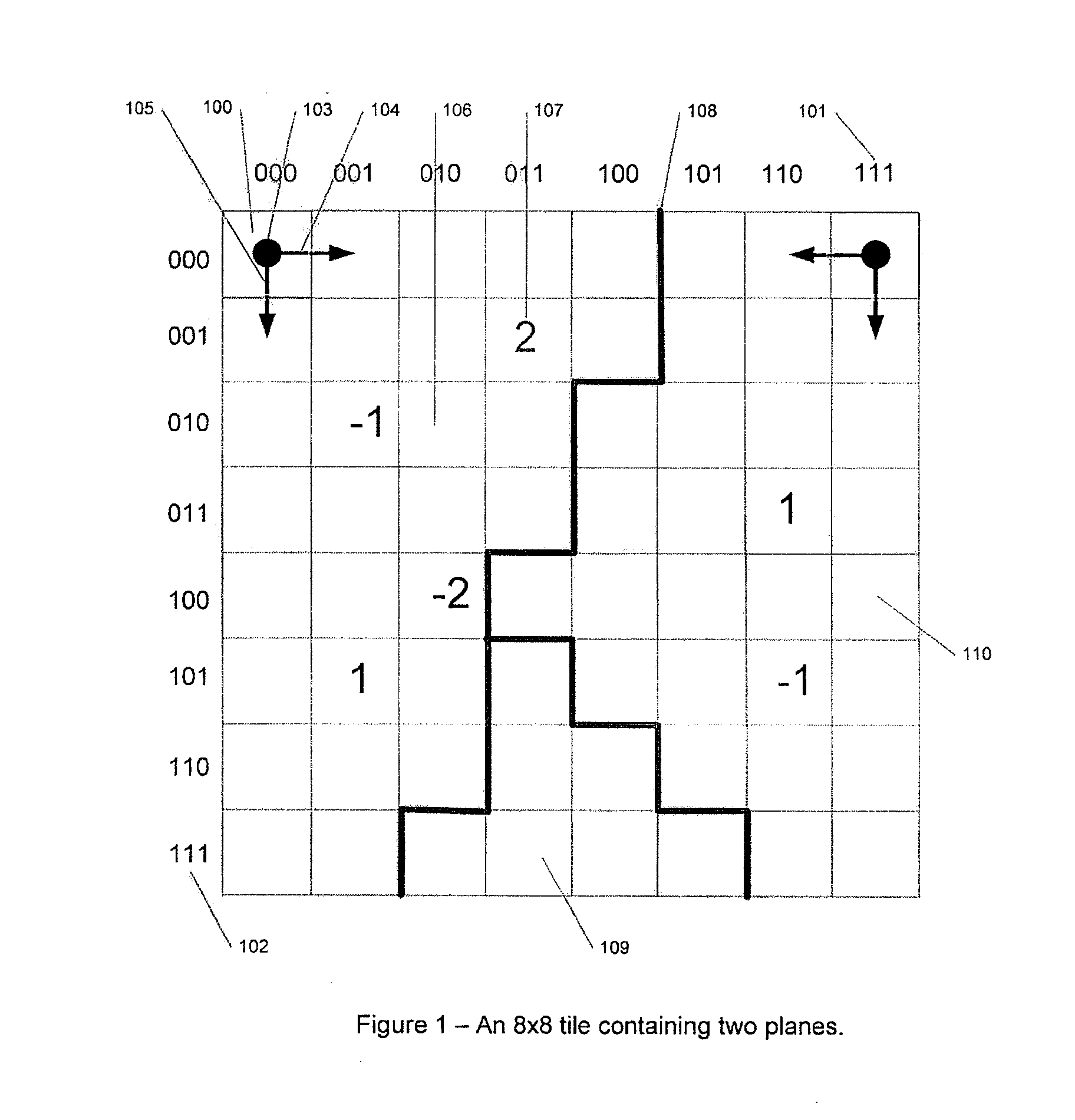
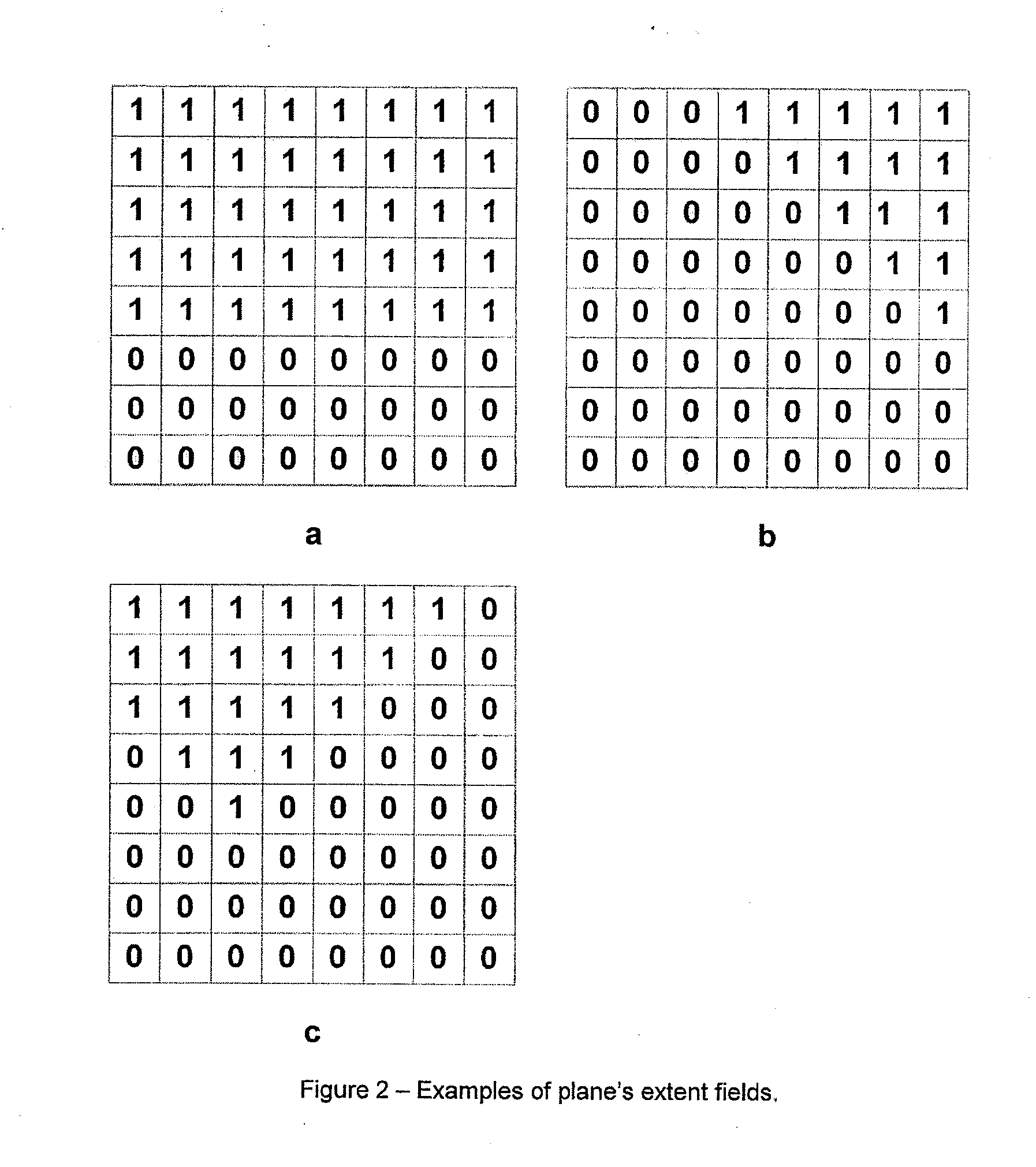

Image

  • Method and apparatus for tile based depth buffer compression
  • Method and apparatus for tile based depth buffer compression
  • Method and apparatus for tile based depth buffer compression

Examples


Embodiment Construction

[0044]One way to reduce the quantity of memory data transferred in each read or write operation to and from a memory, without at the same time increasing data transfer frequency is by holding the data in memory in a compressed format, which is decompressed when read, either into a cache line or used directly. When writing data, either from a cache to memory or directly to memory, the reverse process of compression takes place. Embodiments of the invention use such an approach and are described below.

[0045]Depth buffers are rectangular arrays built up from the depth values from several overlapping polygonal planes. Each location in the array corresponds to a pixel position on the screen and contains a value representing the depth of a polygon fragment currently closest to the viewer at that position. In some depth buffers, each location also contains a stencil value. The embodiments described here only discuss the depth component of this buffer, though it can be extended straightforw...


PUM


Abstract

A method and apparatus are provided for compressing depth buffer data in a three dimensional computer graphics system. The depth buffer data is divided into a plurality of rectangular tiles corresponding to rectangular areas in an associated image. The number of starting point locations in a tile are identified and a difference in depth value determined between each starting point and depth values of each of at least two further locations. Using this information depth values are predicted at a plurality of other locations in the tile and where these predicated values substantially match an actual depth value at location is assigned to a plane associated with respective starting point. Starting point location depth value difference data and plane assignment data for each tile and locations in the tile not assigned to a plane, then stored.

Description

[0001]This invention relates to a method and apparatus for compression of tile-based depth buffer and of the type used in a 3-dimensional computer graphics system, to reduce the volume of data being read from and written to memory used for the depth buffer.BACKGROUND OF THE INVENTION[0002]Three dimensional image computer graphics systems for rendering images are well known. A typical system (e.g. similar to the one represented in FIG. 4) projects and rasterizes polygons 401, and the resulting polygon fragments 402 are sorted in order to determine which are visible to the user and which are hidden. The sorting is typically carried out using a unit known as a depth buffer or z-buffer, 403. Depth or Z buffers are well known to those skilled in the art. Finally, the sorted fragments are written to a frame buffer 407, from where they may be displayed on a screen.[0003]When a polygon is rendered to a frame buffer, the depth (or z-value) of each polygon fragment generated is compared again...

Claims


Application Information

Patent Timeline
Patent Type & Authority Applications(United States)
IPC IPC(8): G06T15/40
CPCG06T9/00G06T2200/28G06T15/40
Inventor FISK, DONALD
Owner IMAGINATION TECH LTD
Why Eureka
Try Eureka