Untransformed display lists in a tile based rendering system

a tile based rendering and display list technology, applied in image memory management, instruments, processor architecture/configuration, etc., can solve the problems of large amount of additional storage and memory bandwidth, and achieve the effect of reducing the amount of storag

Active Publication Date: 2009-10-15
IMAGINATION TECH LTD
View PDF15 Cites 6 Cited by
  • Summary
  • Abstract
  • Description
  • Claims
  • Application Information

AI Technical Summary

Benefits of technology

[0007]Preferred embodiments of the present invention provide a method and apparatus that allow a tile based rendering system to operate with a reduced amount of storage required for tiled screen space geometry. This is accomplished by the use of an untransformed disp

Problems solved by technology

Current tile based systems transform this data into screen space and store the resulting geometry within a parameter buf

Method used


Image

  • Untransformed display lists in a tile based rendering system
  • Untransformed display lists in a tile based rendering system
  • Untransformed display lists in a tile based rendering system

Examples


Embodiment Construction

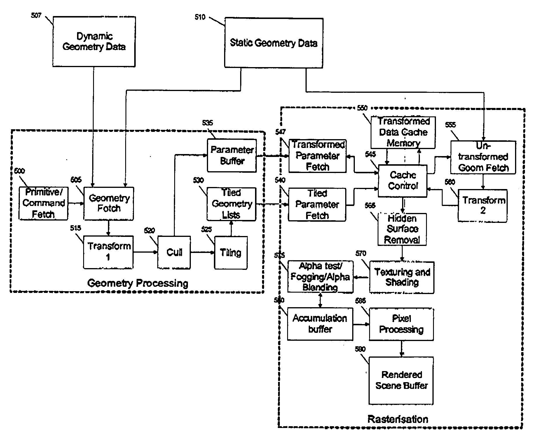
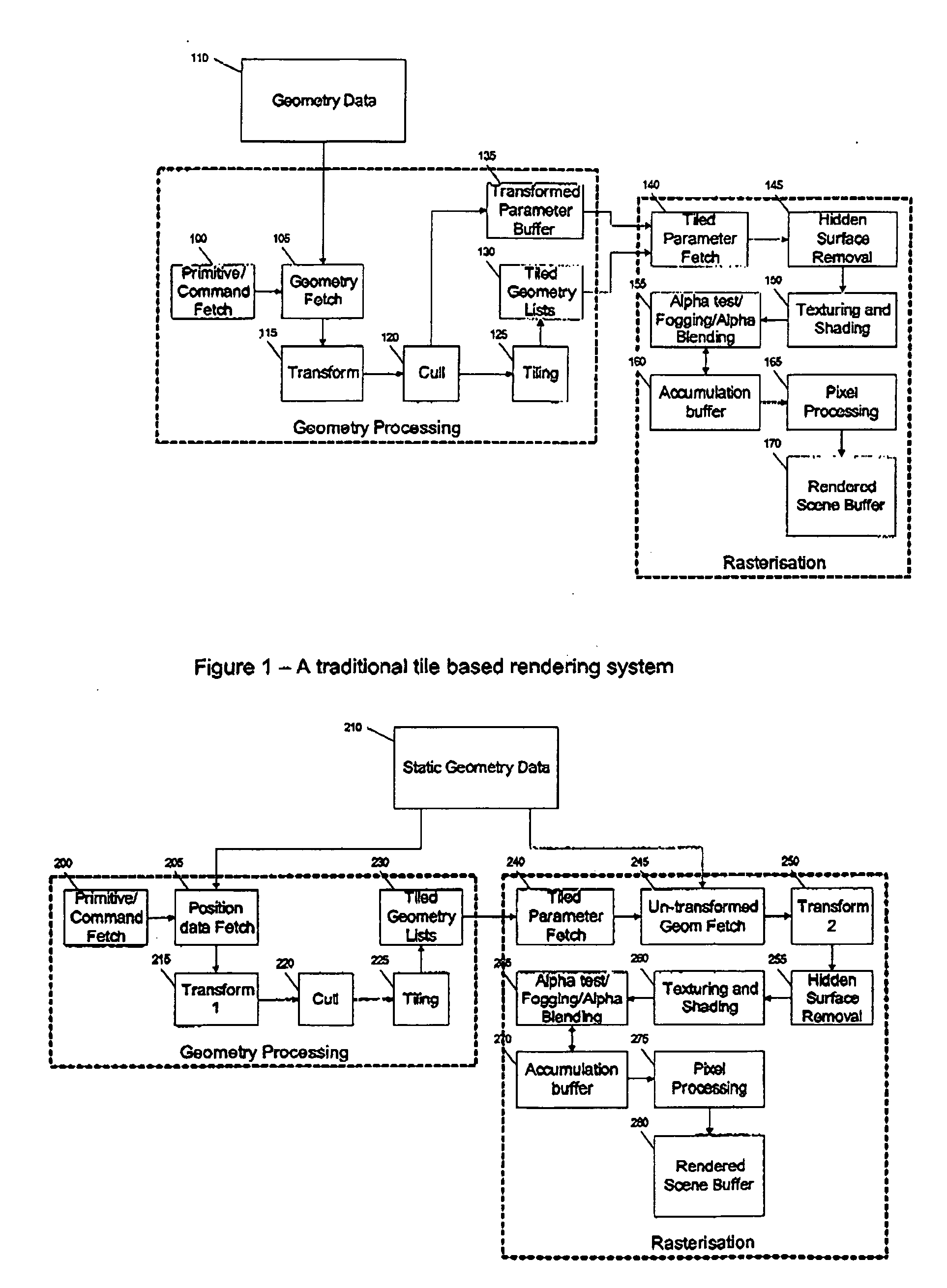
[0014]FIG. 2 illustrates a tile based rendering system that has been modified to support an untransformed display list. During the geometry processing phase a primitive / command fetch unit 200 retrieves command and primitive data from memory and passes this to a position data fetch unit 205 which fetches a position part of static geometry data from memory 210 and passes it to transform 1 unit 215. This transforms the primitive into screen space only i.e. it does not apply any lighting / attribute processing as would occur in the system of FIG. 1. The resulting screen space position data is passed to a culling unit 220 which culls any geometry in the same manner as the system of FIG. 1. Unlike the system of FIG. 1 the culling unit does not write the remaining geometry data to a transformed parameter buffer, instead It only passes the position data of the remaining geometry to a tiling unit 225.

[0015]In the system of FIG. 1, the tiling unit generates references to transformed geometry th...


PUM


Abstract

A three-dimensional computer graphics rendering system allows a tile-based rendering system to operate with a reduced amount of storage required for tiled screen space geometry by using an untransformed display list to represent the screen's geometry.

Description

[0001]This invention relates to a three-dimensional computer graphics rendering system and in particular to methods and apparatus associated with rendering three-dimensional graphic images utilising an untransformed display list within a tile based rendering system.BACKGROUND TO THE INVENTION[0002]Tile based rendering systems are well known, these subdivide an image into a plurality of rectangular blocks or tiles in order to increase efficiency of the rasterisation process.[0003]FIG. 1 illustrates a traditional tile based rendering system. Tile based rendering systems operate in two phases, a geometry processing phase and a rasterisation phase. During the geometry processing phase a primitive / command fetch unit 100 retrieves command and primitive data from memory and passes this to a geometry fetch unit 105 which fetches the geometry data 110 from memory and passes It to a transform unit 115. This transforms the primitive and command data into screen space and applies any lighting / a...

Claims


Application Information

Patent Timeline
IPC IPC(8): G06T15/40G06F13/00G06T15/00
CPCG06T1/60G06T15/005G06T15/80G06T15/08G06T15/40G06T15/04G06T15/405G06T17/10
Inventor HOWSON, JOHN W.
Owner IMAGINATION TECH LTD
Why Eureka
Try Eureka