Three dimensional graphics system with early occlusion culling using Z-ranges

a computer graphics and z-range technology, applied in the field of 3d computer graphics systems, can solve the problems of limiting the rate at which data can be read or written, the complexity of images being rendered has increased considerably, and the memory bandwidth is also a scarce resource, so as to reduce the amount of data written into the display list memory, the effect of reducing the input bandwidth and reducing the amount of data written

Active Publication Date: 2014-04-01
IMAGINATION TECH LTD
View PDF22 Cites 10 Cited by
  • Summary
  • Abstract
  • Description
  • Claims
  • Application Information

AI Technical Summary

Benefits of technology

[0010]The Parameter Management system referred to above allows renders to be performed in a limited amount of memory, but it can have a significant impact on performance compared to a system with a sufficient amount of real memory.
[0011]Embodiments of the invention mitigate the inefficiencies of the Parameter Management system by culling objects before they are stored in the display list. Reducing the amount of data stored in the display list means that fewer partial renders are required to render the scene. As the number of partial renders is reduced, the significant memory bandwidth consumed by the Z Load and Store function is also reduced.
[0014]A second stage of culling, in the parameter fetch stage of the ISP, occurs in a further embodiment. This is at the point at which object pointers are dereferenced, and parameter data is read from the display list memory. This works on a very similar principle to the first stage culling shown in FIG. 3. By storing a little additional information in the object pointer, and by testing this against depth range information maintained in the ISP, it is possible to avoid reading the parameter data for some objects altogether. This type of culling reduces the input bandwidth to the ISP, and the number of objects that the ISP must process, but it does not reduce the amount of data written into the display list memory.
[0015]Unlike the first stage of culling, the second stage works with object pointers that correspond to the tile that is currently being processed by the ISP. The ISP's depth range information can be updated more quickly, and more accurately, than the range information used in the first stage culling, and this allows objects to be culled that were passed by the first stage.

Problems solved by technology

As 3D graphics hardware has become more powerful the complexity of the images being rendered has increased considerably, and can be expected to continue to do so.
Memory bandwidth is also a scarce resource.
Depending upon the memory architecture in use, the limited bandwidth for writing to and reading from the display list memory may limit the rate at which data can be read or written, or it may have an impact on the performance of other subsystems which share the same bandwidth, e.g. texturing.

Method used


Image

  • Three dimensional graphics system with early occlusion culling using Z-ranges
  • Three dimensional graphics system with early occlusion culling using Z-ranges
  • Three dimensional graphics system with early occlusion culling using Z-ranges

Examples


Embodiment Construction

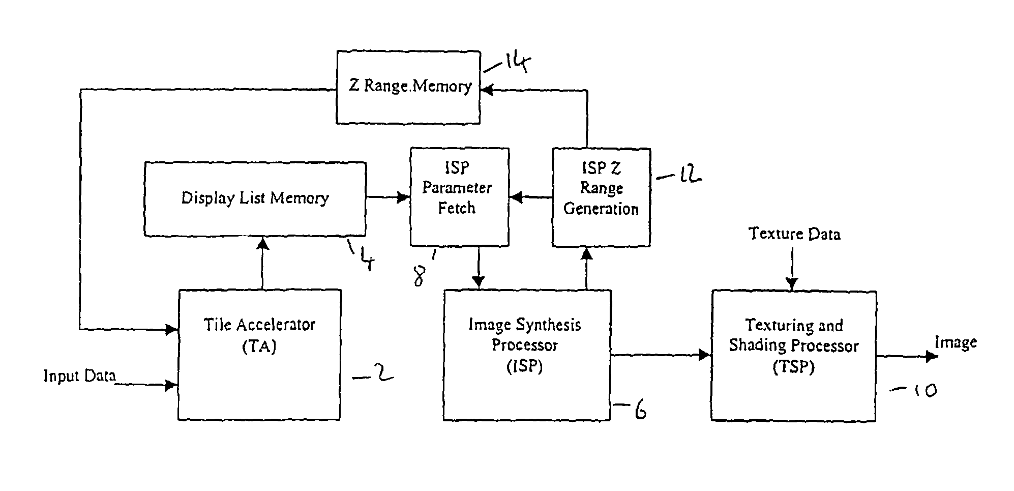
[0028]FIG. 4 is an expanded and modified version of the block diagram of FIG. 1. The ISP Z range generation unit 12 computes the range of Z values stored in the ISP 6 and feeds it back to the first stage of culling, located in the TA2, via the Z range memory 14. A second feedback path sends Z range data to the second stage of culling, located in the ISP parameter fetch unit 8.

[0029]ISP Range Generation

[0030]The embodiment described uses a range of depths that represent the minimum and maximum depths of the objects stored in the ISP 6. This range is computed in the ISP as objects are processed, and represents the actual range of depth values that are stored in the tile at that moment. This range has to be updated constantly, as stored values are continually being replaced and the range may grow and shrink as the scene is rendered. FIGS. 5a) and b) show respectively before and after a situation in which an incoming object is rendered into the pixels which previously determined the max...


PUM


Abstract

An apparatus and a method for generating 3-dimensional computer graphic images. The image is first sub-divided into a plurality of rectangular areas. A display list memory is loaded with object data for each rectangular area. The image and shading data for each picture element of each rectangular area are derived from the object data in the image synthesis processor and a texturizing and shading processor. A depth range generator derives a depth range for each rectangular area from the object data as the imaging and shading data is derived. This is compared with the depth of each new object to be provided to the image synthesis processor and the object may be prevented from being provided to the image synthesis processor independence on the result of the comparison.

Description

CROSS-REFERENCE TO RELATED APPLICATIONS[0001]This application is a continuation of application Ser. No. 11 / 336,685, filed Jan. 20, 2006 now abandoned, which is a continuation of Ser. No. 10 / 202,220, filed Jul. 24, 2002 now abandoned, the disclosures of which are incorporated herein by reference in their entirety.FIELD OF THE INVENTION[0002]This invention relates to 3-dimensional computer graphics systems and in particular to systems of the type described in our British patent numbers 2282682 and 2298111.BACKGROUND OF THE INVENTION[0003]British patent number 2282682 describes a system that uses a ray casting method to determine the visible surfaces in a scene composed of a set of infinite planar surfaces. An improvement to the system is described in UK Patent Application number 2298111, in which the image plane is divided into a number of rectangular tiles. Objects are stored in a display list memory, with ‘object pointers’ used to associate particular objects with the tiles in which...

Claims


Application Information

Patent Timeline
Patent Type & Authority Patents(United States)
IPC IPC(8): G06T15/40
CPCG06T15/40G06T2200/04G06T2200/28G06T15/005G06T15/405
Inventor MORPHET, STEPHEN
Owner IMAGINATION TECH LTD
Why Eureka
Try Eureka