Thermal printer

a printer and thermal technology, applied in the field of thermal printing, can solve the problems of unimproved method and visible impression marks, and achieve the effects of less aggressive grip, less impression marks, and controllable tension differential across the capstan

Active Publication Date: 2012-08-23
KODAK ALARIS INC
View PDF4 Cites 1 Cited by
  • Summary
  • Abstract
  • Description
  • Claims
  • Application Information

AI Technical Summary

Benefits of technology

[0004]Preferred embodiments of the present invention incorporate the use of a less aggressive capstan roller design along with a softer pinch roller to eliminate impression marks in the thermal receiver. To compensate for the less aggressive grip on the receiver, a tension differential across the capstan is controllably decreased. By increasing tension in the receiver on the roll side of the capstan during printing, an acceptable color to color image registration is produced. The capstan uses a straight (longitudinal) knurl pattern with ridges running along the length of the roller parallel to its axis of rotation, as shown in FIGS. 4A-B. The ridges are disposed at a frequency of 10 to 30 ridges per inch. The depth of these ridges being at least 10 microns. Other methods of achieving high traction, non-marking surfaces include the use of plasma coatings, thin elastomeric coatings, and increasing the wrap angle of the receiver around the capstan. In the case of a duplex printer, this invention is applicable whether the printer incorporates a single web path with print heads on both sides of the receiver or separate web paths for individually imaging each side of the sheet.

Problems solved by technology

While this presents no grave problems for a simplex print, since the marks produced are on the back side of the print, for duplex printing this unimproved method leaves noticeable impression marks on thermal receiver media constructed with a dual-sided voided layer.
These impression marks, or depressions, do not allow dye from the dye donor web to reach the receiver media which leaves behind discolored areas on the print, such as white dots.

Method used


Image

  • Thermal printer
  • Thermal printer
  • Thermal printer

Examples


Embodiment Construction

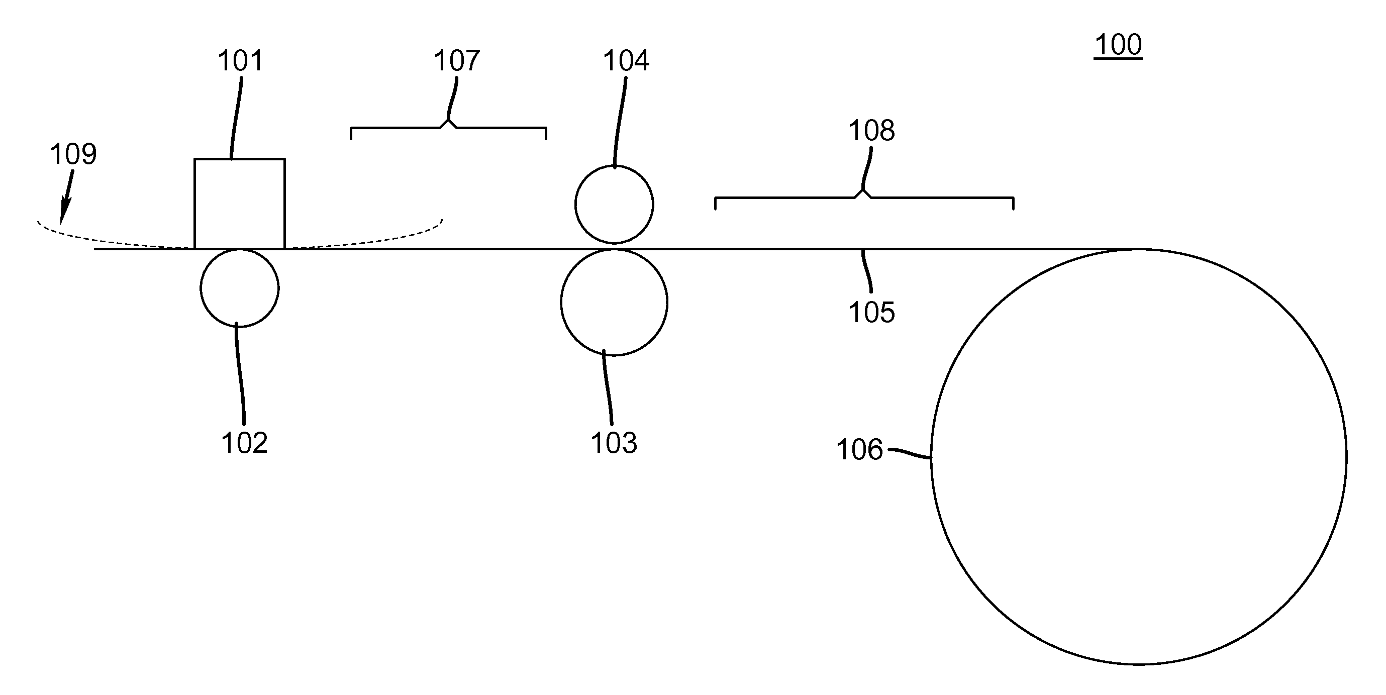
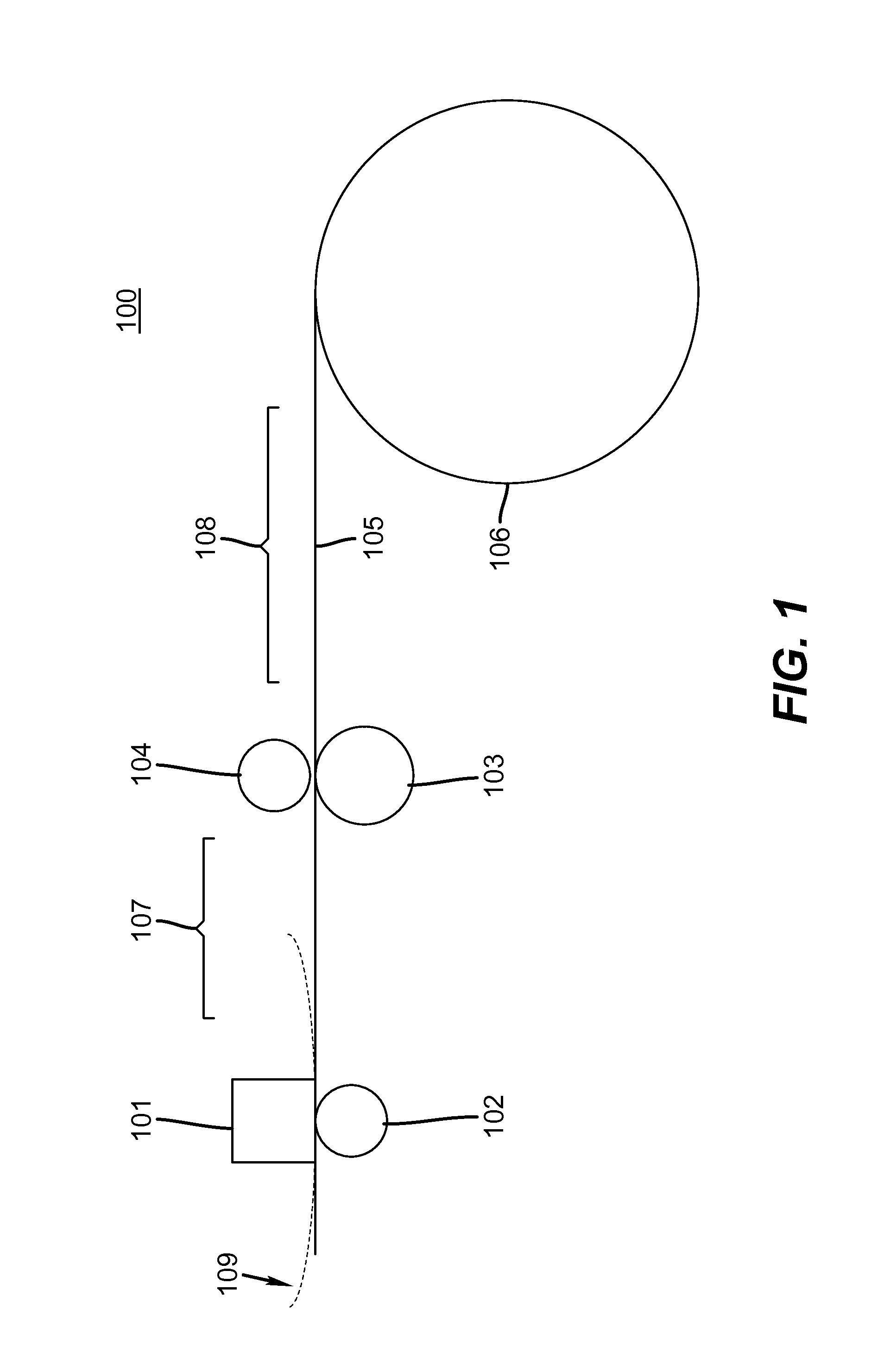
[0018]With reference to FIG. 1 there is illustrated a portion of a thermal printer's drive system. A roll 106 of receiver 105 is fed through a thermal printer 100 as shown by the receiver advancing past thermal print head 101, as fed by thermal roller 102, pinch roller 104 and capstan roller 103. Dye donor web 109 (partially illustrated) is applied onto the receiver in predetermined patterns, as is well known in the art. The receiver is iteratively reversed and printed during several color applications of the dye donor web in the predetermined patterns. Tension in approximate region 107 relative to approximate region 108 affect an ability of the capstan and pinch rollers to effectively control movement of the receiver therethrough.

[0019]A preferred embodiment of the present invention comprises a less aggressive capstan roller 103 design, as is illustrated in FIGS. 4A-B wherein a knurled pattern provides a spike free configuration that does not perforate a surface of receiver 105 as ...


PUM


Abstract

A printer including a supply roll of receiver media and a plurality of rollers to feed the receiver media through the printer. Means for maintaining a preselected tension of the receiver media between the supply roll and a pair of the plurality of rollers includes a motor with a torque limiter. The motor can be attached to the supply roll or to an optional pair of rollers adjacent the supply roll. A capstan roller having a high traction, non-marking surface is used in conjunction with the tension control.

Description

CROSS REFERENCE TO RELATED APPLICATIONS[0001]Reference is made to commonly assigned, co-pending U.S. patent application Ser. No. ______ by Paoletti et al. (Docket K000107) filed of even date herewith entitled “Thermal Printing” the disclosure of which is incorporated herein by reference in its entirety.FIELD OF THE INVENTION[0002]The present invention is directed to thermal printing. In particular, a printer apparatus and method is disclosed for printing on receiver media without damaging the media.BACKGROUND OF THE INVENTION[0003]Currently, most thermal printers achieve acceptable color to color image registration by the use of a capstan roller having sharp peaks, as shown in FIGS. 3A-B, which penetrate the receiver for optimum traction to avoid slippage during receiver transport. While this presents no grave problems for a simplex print, since the marks produced are on the back side of the print, for duplex printing this unimproved method leaves noticeable impression marks on ther...

Claims


Application Information

Patent Timeline
Patent Type & Authority Applications(United States)
IPC IPC(8): B41J2/325
CPCB41J2/325B41J15/16B41J13/02B41J11/0005
Inventor PAOLETTI, RICHARD STEVENGARBACZ, GREGORY JAMES
Owner KODAK ALARIS INC
Why Eureka
Try Eureka