Combine Harvester Unloading System

a harvester and combine technology, applied in the field of combine harvester unloading systems, can solve the problems of difficult to achieve uniform and optimal alignment of the ramp, and achieve the effect of dampening the shock of impa

Inactive Publication Date: 2012-08-23
LAVERDA
View PDF8 Cites 3 Cited by
  • Summary
  • Abstract
  • Description
  • Claims
  • Application Information

AI Technical Summary

Benefits of technology

[0010]In accordance with the invention there is provided a combine harvester unloading system comprising an unloading auger swingable between a stowed position and an unloading position around an upright pivot axis disposed at one end of the auger, and a pivotally mounted auger support cradle moveable between a reception position to engage the underside of the auger when transitioning into the stowed position and a supporting position under the auger when in the stowed position. By pivotally mounting the support cradle, sliding friction between the auger and cradle can be eliminated thus reducing stresses upon any actuator. Furthermore, when in the reception, or tilted, position, the cradle is more tolerant to variation in the height of the auger.
[0012]The system may further comprise biasing means to bias the cradle into the reception position when the auger is in the unloading position, wherein the supported weight of the auger holds the cradle in its supporting position when the auger is in the stowed position. Advantageously, this prevents the cradle from undesirably moving into the supporting position when the auger is deployed thus preventing the auger from engaging with the cradle upon stowing. The biasing means preferably comprises a torsion spring mounted around a pin upon which the cradle pivots.
[0015]The cradle preferably comprises a cushioned contact surface which engages with the underside of the auger. This dampens shock from impact between the auger and the cradle.

Problems solved by technology

The resistance presented by such cradles when sliding the auger into position places large forces upon the actuator connections sometimes leading to failure.
This is compounded by assembly and load variations which make consistent and optimal alignment of the ramp difficult to achieve.

Method used


Image

  • Combine Harvester Unloading System
  • Combine Harvester Unloading System
  • Combine Harvester Unloading System

Examples


Embodiment Construction

[0027]From reading the following description it should be understood that the terms longitudinal and transverse are made in relation to the combine harvester's normal direction of travel. In other words, the term ‘longitudinal’ equates to the fore and aft direction, whereas the term ‘transverse’ equates to the crosswise direction, or left and right. Furthermore, the terms ‘axial’ and‘radial’ are made in relation to a rotating body such as a shaft wherein axial relates to a direction along the rotation axis and radial equates to a direction perpendicular to the rotation axis.

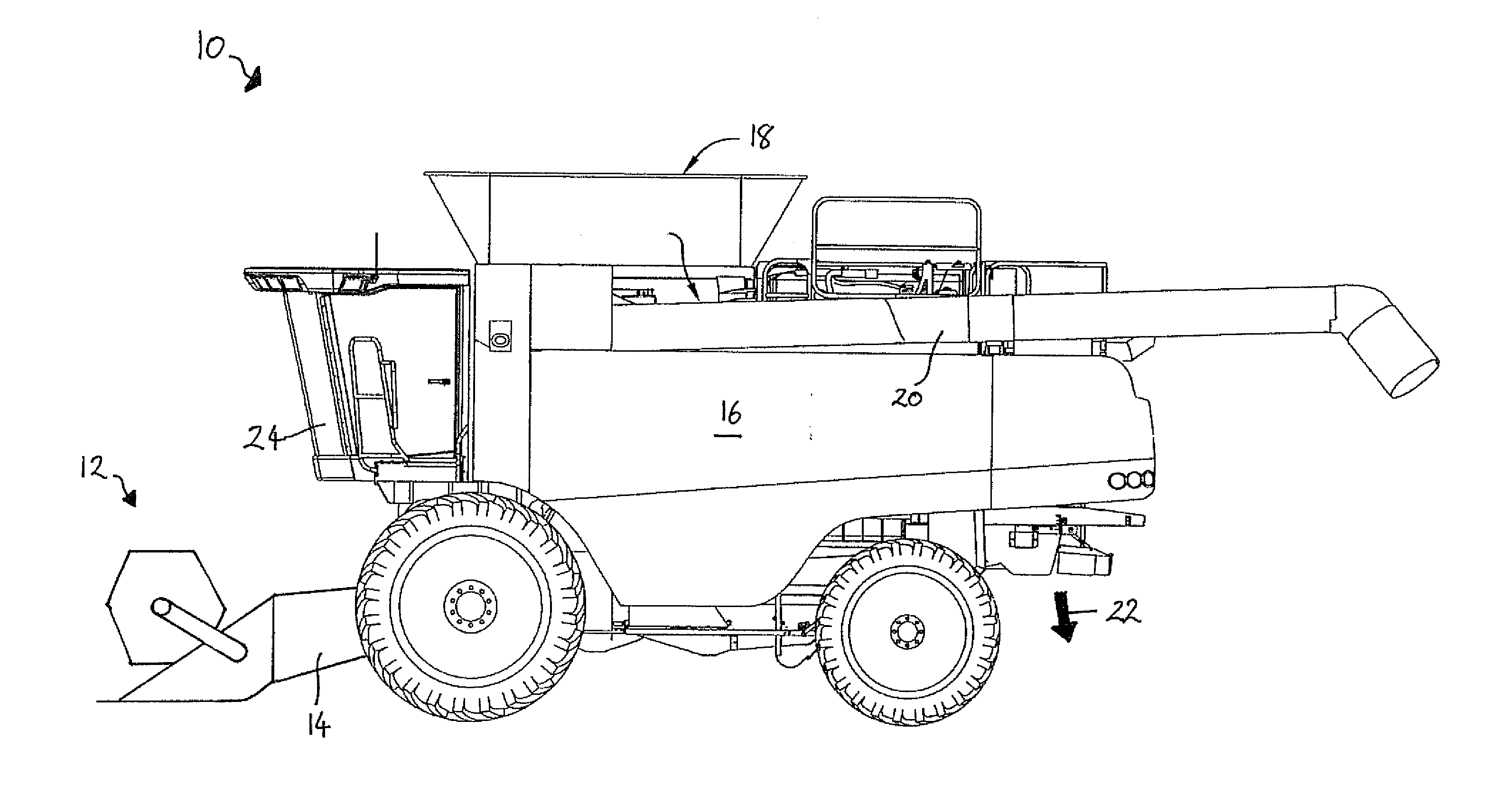
[0028]With reference to FIG. 1, a self-propelled combine harvester 10 comprises a header 12 which cuts and gathers a strip of crop as the combine harvester is driven across a crop field. An elevator section 14 conveys the crop stream from the header 12 into a central processing apparatus 16. Clean grain separated from the crop stream is collected in a storage tank 18 which is periodically emptied into a trailer (...


PUM


Abstract

A combine harvester unloading system is provided in which an unloading auger (20) is swingable between a stowed position and an unloading position around an upright pivot axis disposed at one end of the auger. A pivotally mounted auger support cradle (26) is moveable between a reception position to engage the underside of the auger when transitioning into the stowed position and a supporting position under the auger when in the stowed position.

Description

CROSS-REFERENCE TO RELATED APPLICATION[0001]The present application claims the benefit of and priority from Great Britain Application No. 1102760.4, filed Feb. 17, 2011, the entire disclosure of which is hereby incorporated by reference.FIELD OF THE INVENTION[0002]The invention relates to combine harvester unloading systems that comprise an unloading auger swingable between a stowed position and an unloading position around an upright pivot axis disposed at one end of the auger.BACKGROUND[0003]For many decades, self-propelled combine harvesters have been used by farmers to harvest a wide range of crops including cereals, maize and oil-seed rape. Typically, a combine harvester cuts the crop material, threshes the grain therefrom, separates the grain from the straw, and cleans the grain before storing in an onboard tank. Straw and crop residue is ejected from the rear of the machine.[0004]The collected grain is unloaded into a trailer, parked or driven alongside, via an unloading auge...

Claims


Application Information

Patent Timeline
Patent Type & Authority Applications(United States)
IPC IPC(8): A01D41/12A01F12/46
CPCA01D41/1217
Inventor HOLLATZ, BRIAN JAY
Owner LAVERDA
Why Eureka
Try Eureka