Spinal implant device with fusion cage and fixation plates and method of implanting

a technology of fixation plate and fusion cage, which is applied in the field of spinal implant devices with fusion cage and fixation plate and methods, can solve the problems of many devices that require special surgical tools, and achieve the effects of reducing perioperative morbidity and postoperative patient recovery, facilitating synergistic and optimal interspinous fusion results, and reducing operative tim

Active Publication Date: 2012-08-23
MASSOUDI FARZAD
View PDF13 Cites 18 Cited by
  • Summary
  • Abstract
  • Description
  • Claims
  • Application Information

AI Technical Summary

Benefits of technology

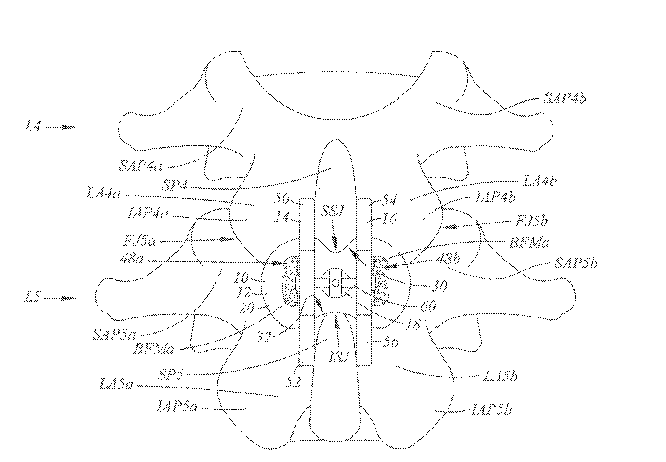
[0009]The spinal implant device allows for simultaneous posterior minimally invasive neural decompression and fusion and allows for instrumentation at all levels of the lumbar spine extending to S1. Advantageously, the spinal implant device incorporates posterior interspinous and facet fusion concepts in a single device. Further, the use of the fixation plates facilitates fixation of the fusion cage in a single device. It is contemplated that it may be utilized in a single or multi level construct and be extended up to three levels in the L1 to S1 region of the spine. An aspect of the invention recognizes that the interspinous interlaminar space unique allows bone fusion of adjacent spinolaminar junctions and facet joints through a single surgical window using a single device.
[0011]An aspect of the invention is that the spinal implant device facilitates synergistic and optimal interspinous fusion results far exceeding the potential of either interspinous or facet fusion devices alone or in combination. It is contemplated that the spinal implant device substantially reduces the operative time, perioperative morbidity and postoperative patient recovery in comparison to other prior devices and procedures whether alone or in combination with each other. Further, the design allows for interspinous and facet fusion without the need for pedicle or facet screws which may result in iatrogenic destabilization of the motion segment. Moreover, the design avoids transverse process fusion, which is contemplated to be highly invasive.

Problems solved by technology

Further, many devices require specialized surgical tools.

Method used


Image

  • Spinal implant device with fusion cage and fixation plates and method of implanting
  • Spinal implant device with fusion cage and fixation plates and method of implanting
  • Spinal implant device with fusion cage and fixation plates and method of implanting

Examples


Embodiment Construction

[0043]The detailed description set forth below in connection with the appended drawings is intended as a description of certain embodiments of the present disclosure, and is not intended to represent the only forms that may be developed or utilized. The description sets forth the various functions in connection with the illustrated embodiments, but it is to be understood, however, that the same or equivalent functions may be accomplished by different embodiments that are also intended to be encompassed within the scope of the present disclosure. It is further understood that the use of relational terms such as top and bottom, first and second, and the like are used solely to distinguish one entity from another without necessarily requiring or implying any actual such relationship or order between such entities.

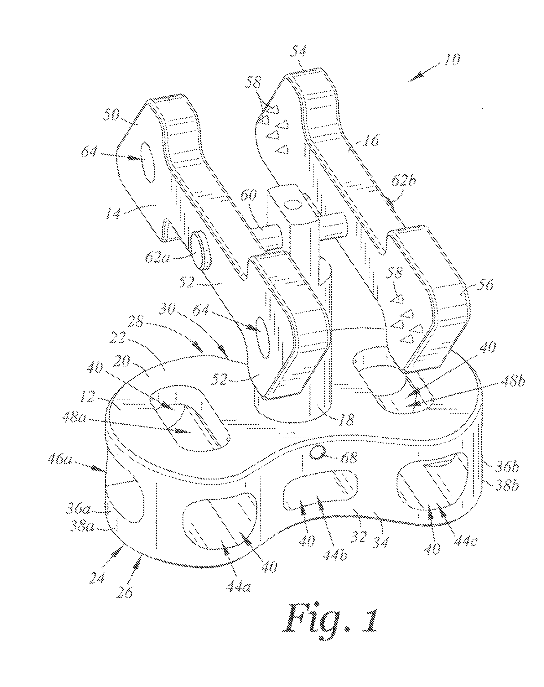
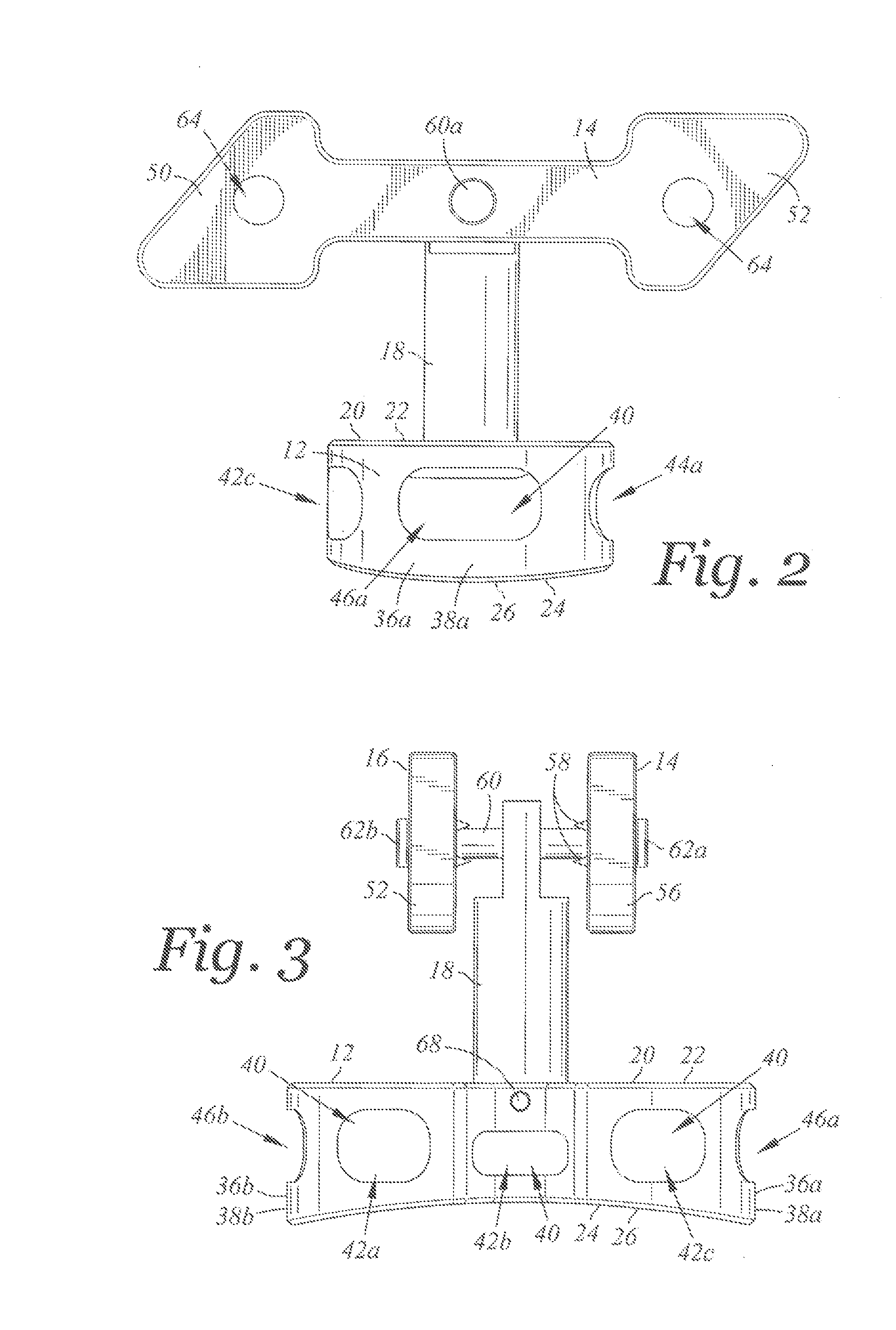
[0044]Referring now to FIG. 1, there is depicted a perspective view of a spinal implant device 10 according to an embodiment of the invention. FIG. 2 is a side view of the spi...


PUM


Abstract

There is provided a spinal implant device for placement between adjacent spinous processes and a pair of opposing facet joints. The spinal implant device includes a fusion cage, first and second fixation plates and a connector for connecting the cage to the plates. The fusion cage includes a superficial face, a deep face, superior and inferior saddle portions, and opposing cage ends. Each cage end defining a facet fusion surface sized and configured to respectively contact the opposing facet joints. The first and second fixation plate are sized and configured to extend along and in contact with the adjacent spinous processes. A method of implanting the device is provided. In another embodiment the device includes the fusion cage.

Description

CROSS-REFERENCE TO RELATED APPLICATIONS[0001]Not ApplicableSTATEMENT RE: FEDERALLY SPONSORED RESEARCH / DEVELOPMENT[0002]Not ApplicableBACKGROUND[0003]1. Technical Field[0004]The present disclosure relates generally to spinal implant devices. More particularly, the present disclosure relates to spinal implant devices with a fusion cage and fixation plates and methods of implanting the same.[0005]2. Related Art[0006]There have been a myriad of spinal implant devices and techniques for treating spinal conditions that focus on fusion of the various levels of the lumbar spine. Moreover, a myriad of fixation devices and techniques have been implemented. Such fixation techniques range from use of peticle or facet screws with attached connecting rods to interspinous devices interacting with the spinous processes (such as spacers attaching the spinous processes with screw or bands). Implantation techniques may require multiple procedures which may be posterior and / or lateral in nature. Furthe...

Claims


Application Information

Patent Timeline
Patent Type & Authority Applications(United States)
IPC IPC(8): A61B17/70A61B17/88
CPCA61B17/7064A61B17/7068A61B17/7067
Inventor MASSOUDI, FARZAD
Owner MASSOUDI FARZAD
Why Eureka
Try Eureka