
Distinguishing between sensor and process faults in a sensor network with minimal false alarms using a bayesian network based methodology

a sensor network and network technology, applied in the field of condition-based maintenance, monitoring, diagnosis and maintenance of various systems, can solve the problems of inability to distinguish between the two, false alarms with regard to the operational state, the estimated health or remaining useful life of the sensor network, and the complexity of establishing a framework to best utilize the available sensing resources at any given time, so as to achieve the effect of greatly reducing the overall life-cycle cost of the system

Inactive Publication Date: 2012-08-23
BOARD OF RGT THE UNIV OF TEXAS SYST
View PDF8 Cites 52 Cited by
  • Summary
  • Abstract
  • Description
  • Claims
  • Application Information

AI Technical Summary

Benefits of technology

[0008]By distinguishing between these different scenarios and identifying with some level of confidence the precise sour

Problems solved by technology

However, establishing a framework to manage and best utilize the available sensing resources at any given time is a quite complex task.
In such cases, using data from sensors with faults can result in incorrect estimates of the monitored system's state and / or capabilities and cause false alarms with regards to the operational state, its estimated health or remaining useful life.
In the worst case scenario, a sensor as well as the system it is monitoring may be developing incipient faults and it may be impossible to distinguish between the two.
But abnormal sensor behavior may sometimes be masked by such subtle changes in operating conditions, especially for anomalies like drift.

Method used


Image

  • Distinguishing between sensor and process faults in a sensor network with minimal false alarms using a bayesian network based methodology
  • Distinguishing between sensor and process faults in a sensor network with minimal false alarms using a bayesian network based methodology
  • Distinguishing between sensor and process faults in a sensor network with minimal false alarms using a bayesian network based methodology

Examples


Embodiment Construction

[0026]In the following description, numerous specific details are set forth to provide a thorough understanding of the present invention. However, it will be apparent to those skilled in the art that the present invention may be practiced without such specific details. In other instances, well-known circuits have been shown in block diagram form in order not to obscure the present invention in unnecessary detail. For the most part, details considering timing considerations and the like have been omitted inasmuch as such details are not necessary to obtain a complete understanding of the present invention and are within the skills of persons of ordinary skill in the relevant art.

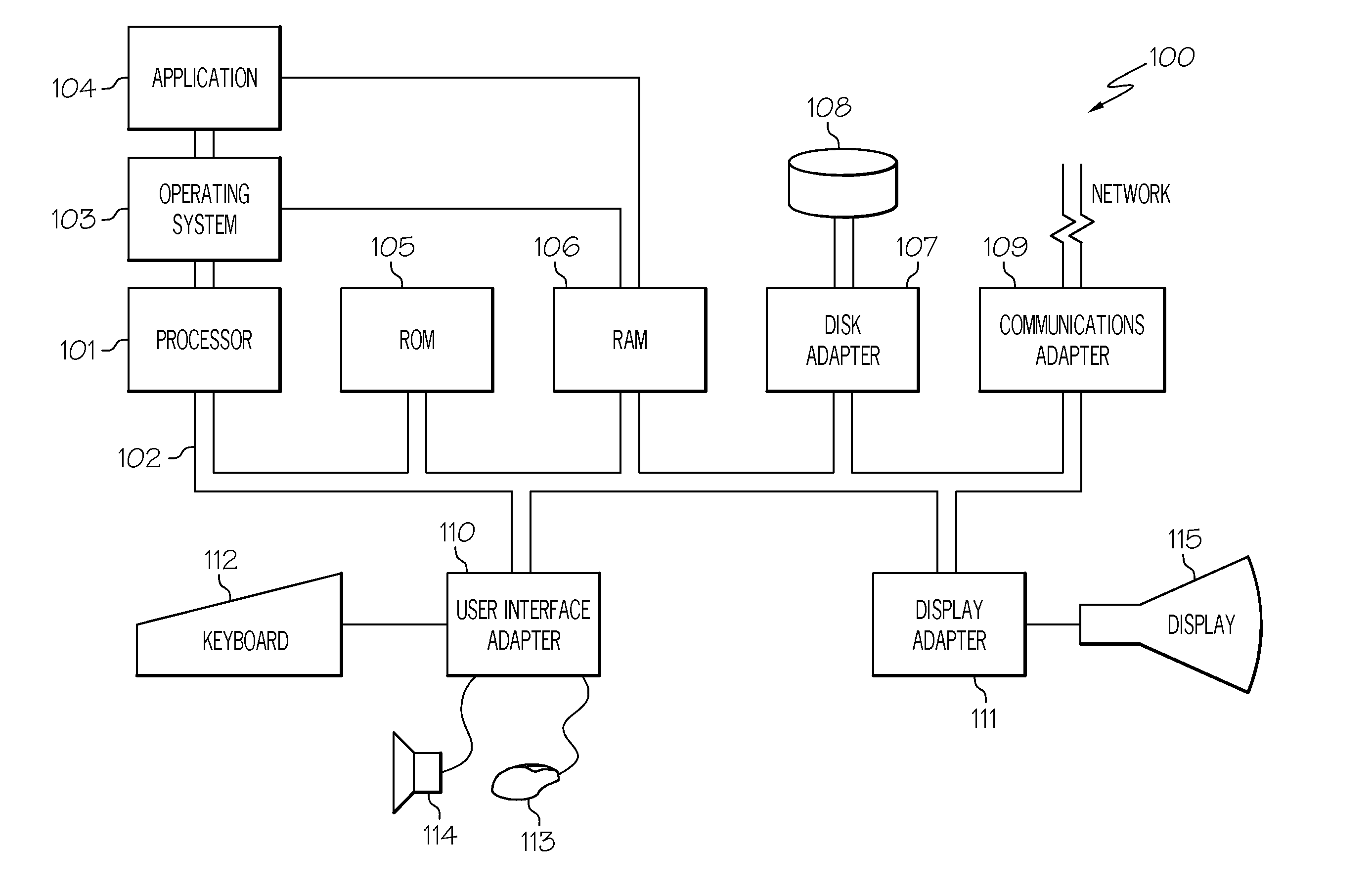
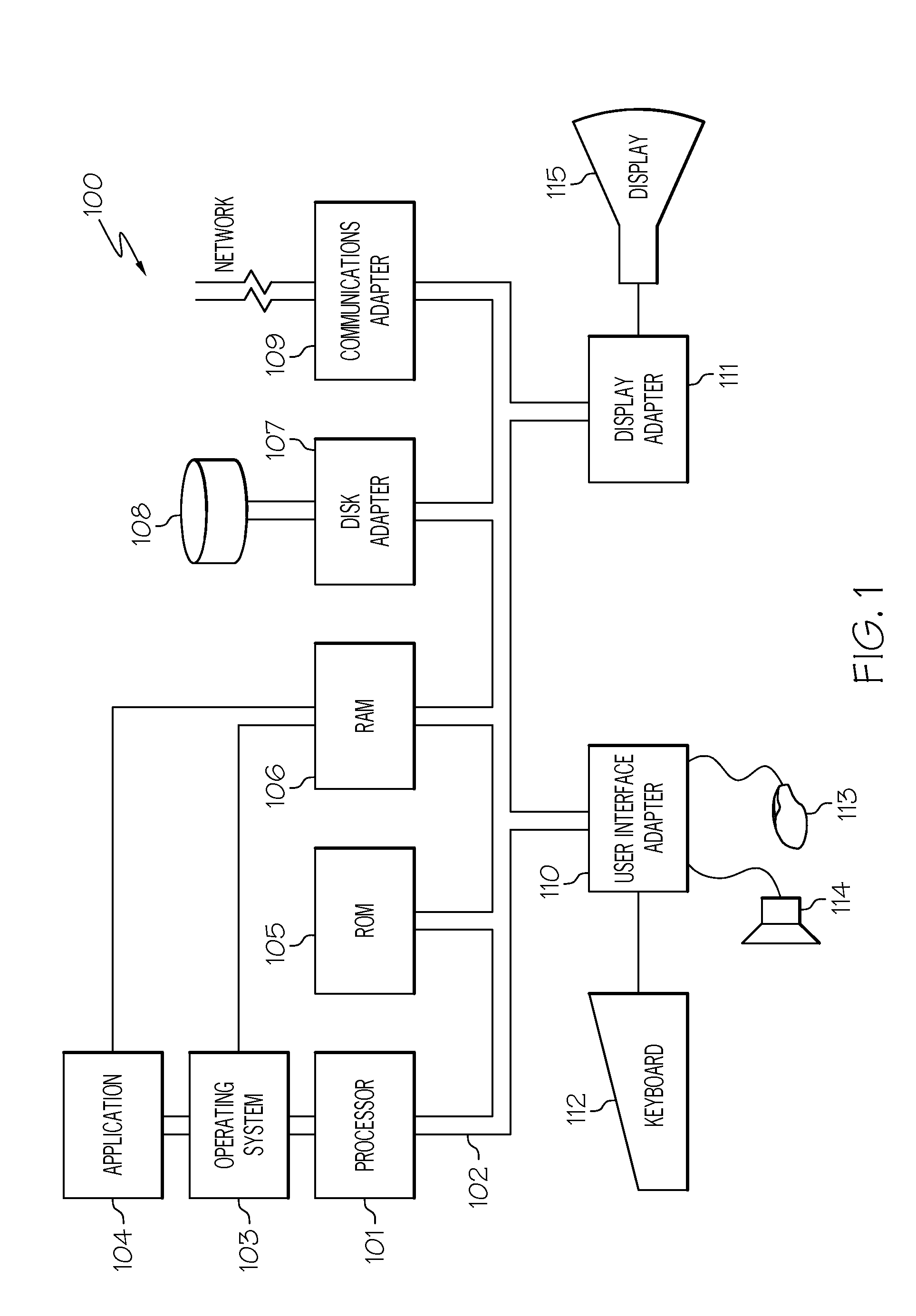
[0027]Referring now to the Figures in detail, FIG. 1 illustrates an embodiment of a hardware configuration of a computer system 100 which is representative of a hardware environment for practicing the present invention. In one embodiment, computer system 100 is attached to sensors (not shown), sensing activit...


PUM


Abstract

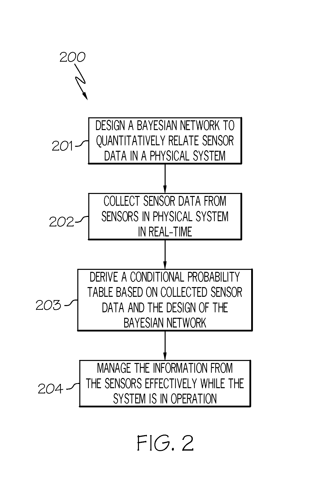
A method, system and computer program product for distinguishing between a sensor fault and a process fault in a physical system and use the results obtained to update the model. A Bayesian network is designed to probabilistically relate sensor data in the physical system which includes multiple sensors. The sensor data from the sensors in the physical system is collected. A conditional probability table is derived based on the collected sensor data and the design of the Bayesian network. Upon identifying anomalous behavior in the physical system, it is determined whether a sensor fault or a process fault caused the anomalous behavior using belief values for the sensors and processes in the physical system, where the belief values indicate a level of trust regarding the status of its associated sensors and processes not being faulty.

Description

CROSS-REFERENCE TO RELATED APPLICATIONS[0001]This application is related to the following commonly owned co-pending U.S. patent application:[0002]Provisional Application Ser. No. 61 / 445,614, “Distinguishing Between Sensor and Process Faults in a Sensor Network with Minimal False Alarms Using a Bayesian Network Based Methodology,” filed Feb. 23, 2011, and claims the benefit of its earlier filing date under 35 U.S.C. §119(e).GOVERNMENT INTERESTS[0003]The U.S. Government has certain rights in this invention pursuant to the terms of the Department of Defense-Office of Naval Research Grant No. N0014-09-1-0427.TECHNICAL FIELD[0004]The present invention relates to monitoring, diagnosing and condition-based maintenance of various systems, and more particularly to using a Bayesian network based methodology to distinguish between sensor and process faults in a sensor network with minimal false alarms.BACKGROUND[0005]Various physical systems employ a suite of sensors to enable comprehensive mo...

Claims


Application Information

Patent Timeline
IPC IPC(8): G06F17/18G01R31/00G06F19/00
CPCG05B23/0262G05B23/0254
Inventor ASHOK, PRADEEPKUMARKRISHNAMOORTHY, GANESHTESAR, DELBERT
Owner BOARD OF RGT THE UNIV OF TEXAS SYST
Learn More