Connectors for use with polarization-maintaining and multicore optical fiber cables

a technology of optical fiber and connectors, applied in the field of fiber optics, can solve the problems of unsatisfactory prior work, difficult design of optical fiber connectors, and the problem of fibers requiring rotational alignment,

Active Publication Date: 2012-08-30
OFS FITEL LLC
View PDF6 Cites 52 Cited by
  • Summary
  • Abstract
  • Description
  • Claims
  • Application Information

AI Technical Summary

Benefits of technology

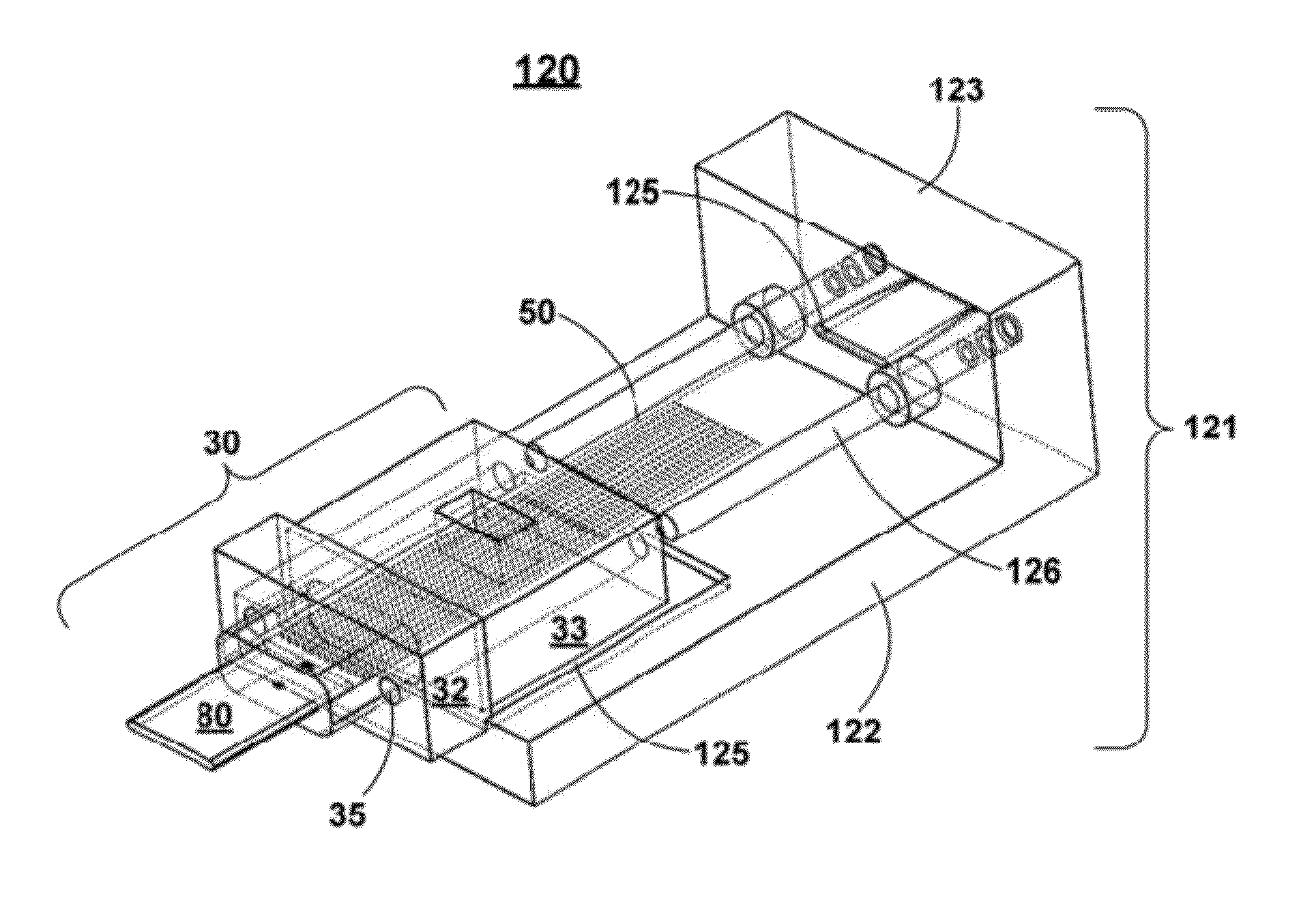
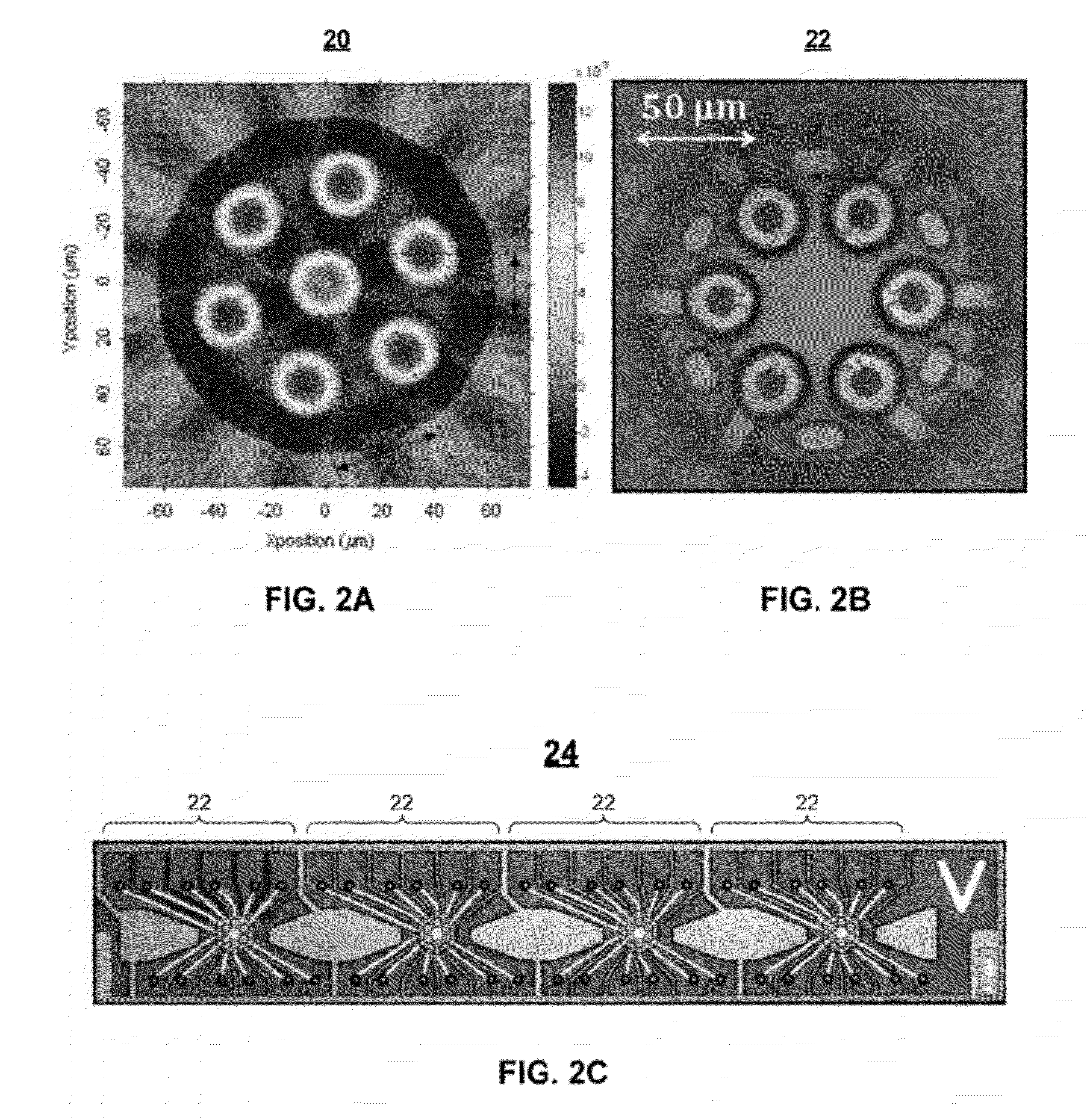
[0012]Another aspect of the invention provides a fiber array block having a plurality of V-shaped grooves extending across an outer surface and terminating at an endface. The plurality of V-shaped grooves are shaped to guide a respective plurality of fibers having one or more flat sides indicative of its rotational orientation. A lid is installable across the plurality of V-shaped grooves, thereby holding in place fibers that have been loaded into the plurality of V-shaped grooves. The substrate, lid, and fibers are configured such that installation of the lid over fibers that have been loaded into the plurality of V-shaped grooves results in alignment of the loaded fibers according to a desired rotational orientation.

Problems solved by technology

The design of optical fiber connectors has been challenging for a number of reasons, including the small diameter of a typical optical fiber, and the need for a secure, low-loss connection between fibers.
A further challenge has been presented by multi-fiber optical cables, which have required the development of connectors that can accommodate a plurality of closely-spaced individual fibers.
One issue that has not been satisfactorily addressed by the prior art is the alignment issue presented by fibers requiring rotational alignment.
One particularly challenging problem to be addressed is how to provide rotationally aligned connectorization for optical cables containing closely spaced arrays of these types of fibers.

Method used


Image

  • Connectors for use with polarization-maintaining and multicore optical fiber cables
  • Connectors for use with polarization-maintaining and multicore optical fiber cables
  • Connectors for use with polarization-maintaining and multicore optical fiber cables

Examples


Embodiment Construction

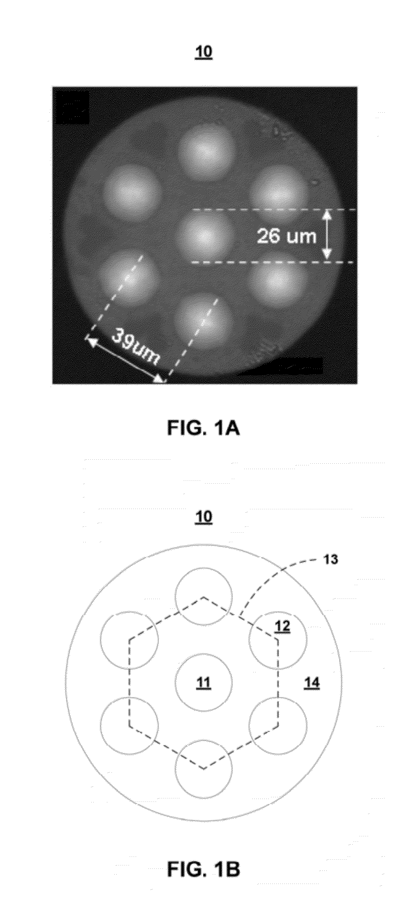
[0046]Aspects of the invention are directed to connectors for use with polarization-maintaining and multicore fiber cables. As used herein, the term “polarization-maintaining fiber” (PMF) refers generally to an optical fiber that is designed to have a high birefringence, whereby light travels at significantly different speeds along first and second transmission axes. As used herein, the term “multicore fiber” (MCF) refers generally to an optical fiber having a plurality of individual cores that extend longitudinally through a common cladding, thereby providing a corresponding plurality of parallel data transmission channels. Various exemplary PMFs and MCFs are depicted herein, having different cross-sectional profiles. It will be appreciated that the structures and techniques described herein may be implemented using PMFs or MCFs having configurations different from those specifically depicted herein.

[0047]The present specification is divided into two sections. Section A describes c...


PUM

PropertyMeasurementUnit
central angleaaaaaaaaaa
refractive index profileaaaaaaaaaa

Abstract

An optical fiber ferrule has a plurality of guide holes therein for guiding a respective plurality of flat-sided fibers at an end of a multifiber optical fiber cable. The fibers' flat sides identify a particular rotational orientation of the fiber. Rotational alignment is achieved by urging the fibers' flat sides against a corresponding reference surface within the ferrule or within an alignment fixture. Also described is a fiber array block having a plurality of V-shaped grooves extending across an outer surface and terminating at an endface. The V-shaped grooves are shaped to guide a respective plurality of flat-sided fibers. A lid is installable across the plurality of V-shaped grooves, over fibers that have been loaded therein.

Description

CROSS REFERENCE TO RELATED APPLICATIONS[0001]The present application is a continuation-in-part of co-pending U.S. patent application Ser. No. 13 / 049,794, filed on Mar. 16, 2011.[0002]U.S. patent application Ser. No. 13 / 049,794 claims the priority benefit of U.S. Provisional Patent Application Ser. No. 61 / 314,165, filed on Mar. 16, 2010.[0003]The above applications are owned by the assignee of the present application, and are incorporated herein by reference in their entirety.BACKGROUND OF THE INVENTION[0004]1. Field of the Invention[0005]The present invention relates generally to the field of fiber optics, and in particular to improved connectors for polarization-maintaining and multicore optical fiber cables.[0006]2. Background Art[0007]Optical fiber connectors are used to join optical fibers where a connect / disconnect capability is required. The design of optical fiber connectors has been challenging for a number of reasons, including the small diameter of a typical optical fiber,...

Claims


Application Information

Patent Timeline
Patent Type & Authority Applications(United States)
IPC IPC(8): G02B6/36G02B6/00G02B6/24G02B6/024
CPCG02B6/3851Y10T29/4978G02B6/3893G02B6/3885G02B6/3652G02B6/3861G02B6/3863Y10T29/49194
Inventor BRADLEY, KELVIN B.KIM, JINKEESANDELS, GREGORY A.
Owner OFS FITEL LLC
Why Eureka
Try Eureka