Two-stage centrifugal pump

a centrifugal pump and two-stage technology, applied in the field of centrifugal pumps, can solve the problems of large external diameter, inability to fit as easily in the motor vehicle as the main centrifugal pump, and increase the cost of the pump, so as to achieve the effect of simplifying the assembly method

Inactive Publication Date: 2012-08-30
ROBERT BOSCH GMBH
View PDF3 Cites 6 Cited by
  • Summary
  • Abstract
  • Description
  • Claims
  • Application Information

AI Technical Summary

Benefits of technology

[0004]It is therefore an object of the invention to specify a centrifugal pump which, with the same build-up of pressure, has compact external dimensions and is simple to assemble.

Problems solved by technology

A single-stage centrifugal pump in principle suitable for these requirements, with a higher capacity than the main centrifugal pump, is usually substantially more expensive and has a larger external diameter, so that it cannot as readily be fitted in the motor vehicle as the main centrifugal pump.

Method used


Image

  • Two-stage centrifugal pump
  • Two-stage centrifugal pump
  • Two-stage centrifugal pump

Examples


Embodiment Construction

[0023]Identical or mutually corresponding elements bear the same designations in all the figures.

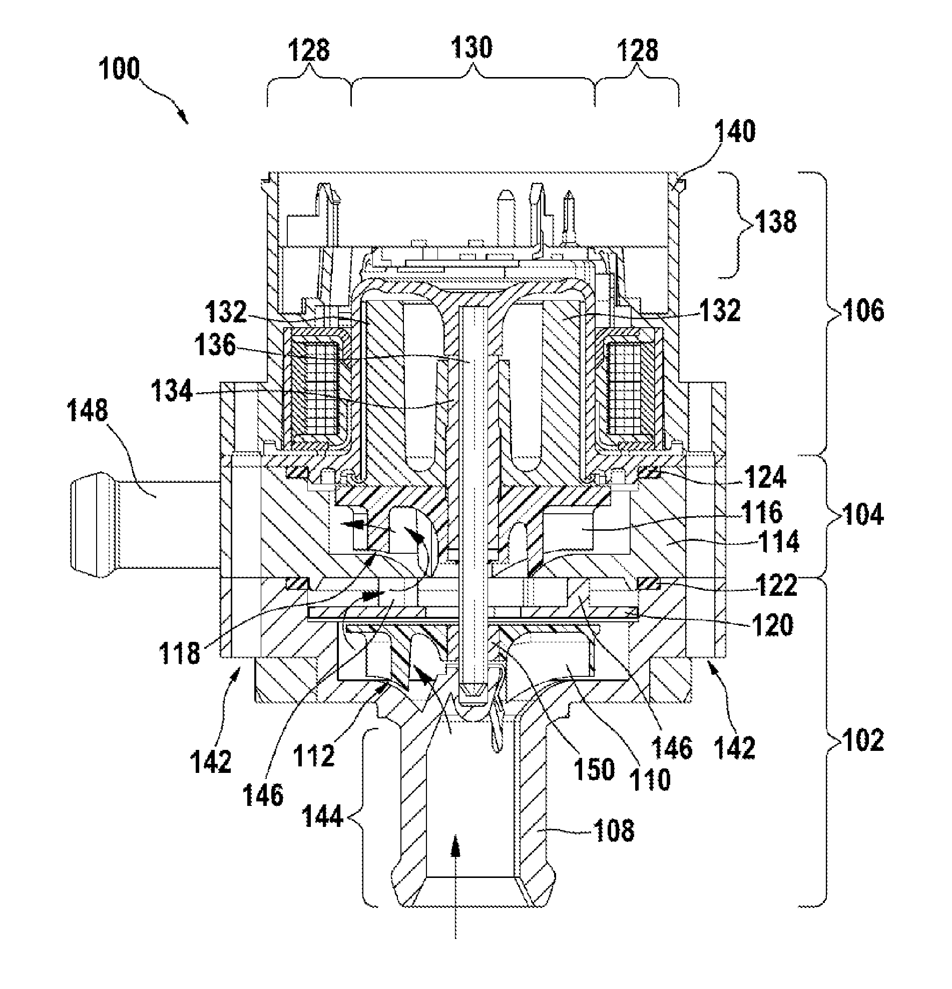
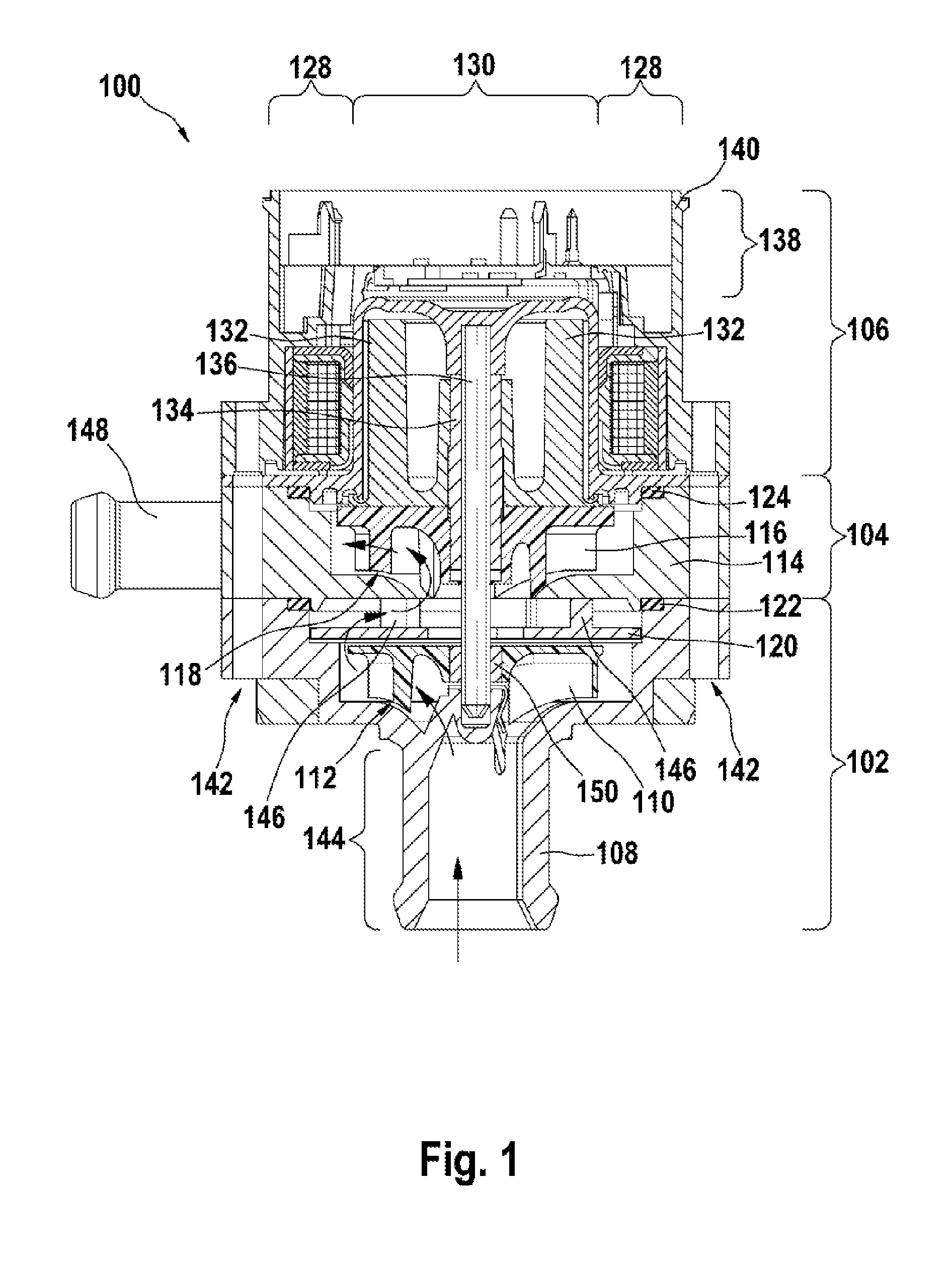
[0024]FIG. 1 shows a longitudinal section through the centrifugal pump 100. The centrifugal pump 100 comprises a first pump stage 102, a second pump stage 104 and an electric motor 106 as drive device. The first pump stage 102 comprises a first pump housing 108 and a first impeller 110, between which a first gap region 112 is formed. The second pump stage 104 comprises a second pump housing 140 and a second impeller 116, between which a second gap region 118 is formed. In a region between the first pump stage 102 and the second pump stage 104 there is arranged an intermediate housing 120. The first pump housing 108 rests on the second pump housing 114 and is sealed off with respect to the latter by means of an O-ring 122. The second pump housing 114 rests on the electric motor 106 and is sealed off with respect to the latter in a corresponding way by means of an O-ring 124.

[0025]The elec...


PUM

PropertyMeasurementUnit
torqueaaaaaaaaaa
pressureaaaaaaaaaa
diameteraaaaaaaaaa

Abstract

The invention relates to a centrifugal pump (100), in particular for a coolant in a motor vehicle, comprising a first centrifugal pump stage (102) having a first pump housing (108), and a first impeller (110) rotatably mounted therein, and to a drive device (106) for coaxially driving the first impeller. A second centrifugal pump stage (104) has a second pump housing (114) and a second impeller (116) rotatably mounted therein and an intermediate housing (120) is located between the first and the second pump housing (108, 114) for diverting a fluid flow dispersed by the first impeller to an inlet region of the second impeller.

Description

BACKGROUND OF THE INVENTION[0001]The invention relates to a centrifugal pump. In particular, the invention relates to a two-stage centrifugal pump for a coolant in a motor vehicle.[0002]Single-stage centrifugal pumps, for example for conveying a coolant, are known in various variations. For example, EP 1850448 A1 shows a single-stage centrifugal pump in which a rotor of an electric motor driving the centrifugal pump is designed to be integrated with an impeller of the centrifugal pump.[0003]In complex environments such as in a motor vehicle, varying requirements are placed on a centrifugal pump. For example, modern motor vehicles comprise diverse additional cooling circuits, for example for intake air cooling or for cooling electronic modules, which can require a higher build-up of pressure with the same or lower delivery volume as compared with a centrifugal pump used in a main cooling circuit. A single-stage centrifugal pump in principle suitable for these requirements, with a hig...

Claims


Application Information

Patent Timeline
Patent Type & Authority Applications(United States)
IPC IPC(8): F04D17/08B23P15/00
CPCF04D1/06Y10T29/49002F04D29/426F04D29/2222F04D29/22F04D29/42
Inventor HEIN, BERNDHEIER, CHRISTOPHTHIERY, JEROME
Owner ROBERT BOSCH GMBH
Why Eureka
Try Eureka