Plastic element, piston pump, and assembly method

a technology of piston pump and plastic element, which is applied in the direction of valve housing, positive displacement liquid engine, liquid fuel engine, etc., to achieve the effect of convenient assembly

Inactive Publication Date: 2010-09-30
ROBERT BOSCH GMBH
View PDF20 Cites 6 Cited by
  • Summary
  • Abstract
  • Description
  • Claims
  • Application Information

AI Technical Summary

Benefits of technology

[0007]The invention is based on the concept of manufacturing the plastic components that are separate in the operation of the piston pump, that is, the inlet valve cap and the inlet valve element, as a one-piece plastic element, and the one-piece plastic element has at least one rated breaking point by whose separation the plastic element is split into the components separate from one another, the inlet valve cap and the inlet valve element. The embodiment of the preferably cup-shaped inlet valve cap and of the inlet valve element in an initially one-piece plastic element, which is preferably split only during assembly, in particular automatically, by separation of the rated breaking point, into the inlet valve cap and the inlet valve element that is separate from the inlet valve cap, offers a number of advantages. For instance, manufacturing a one-piece plastic element is substantially more economical than separately manufacturing an inlet valve cap and an inlet valve element. Moreover, the assembly of a piston pump is facilitated substantially by the use of such a plastic element, since instead of two separate components, only a one-piece plastic element has to be manipulated. Moreover, the one-piece embodiment of the plastic element ensures that the components of it, the inlet valve cap and the inlet valve element, are embodied of exactly the same material, which is feasible only with difficulty in the case of separate manufacture. By this provision, an identical wear behavior of the components is guaranteed.
[0008]An embodiment of the one-piece plastic element in which this part is made as an injection-molded part is particularly advantageous. The manufacture of the plastic element as an injection-molded part makes it easily possible to adhere to close tolerances and to produce the plastic element as a mass-produced that can be made from bulk material.
[0016]An embodiment of the piston pump or of the inlet valve of the piston pump, in which the closing spring element of the inlet valve, which is preferably embodied as a helical spring, in the installed state surrounds a central portion of the inlet valve cap is especially advantageous. In other words, in the assembled state of the piston pump, a preferably at least approximately cylindrical central portion protrudes axially into, the closing spring element. Thus the closing spring element prevents unintentional bending open of at least one circumferential wall portion of the preferably cup-shaped inlet valve cap.

Problems solved by technology

Moreover, the one-piece embodiment of the plastic element ensures that the components of it, the inlet valve cap and the inlet valve element, are embodied of exactly the same material, which is feasible only with difficulty in the case of separate manufacture.

Method used


Image

  • Plastic element, piston pump, and assembly method
  • Plastic element, piston pump, and assembly method

Examples


Embodiment Construction

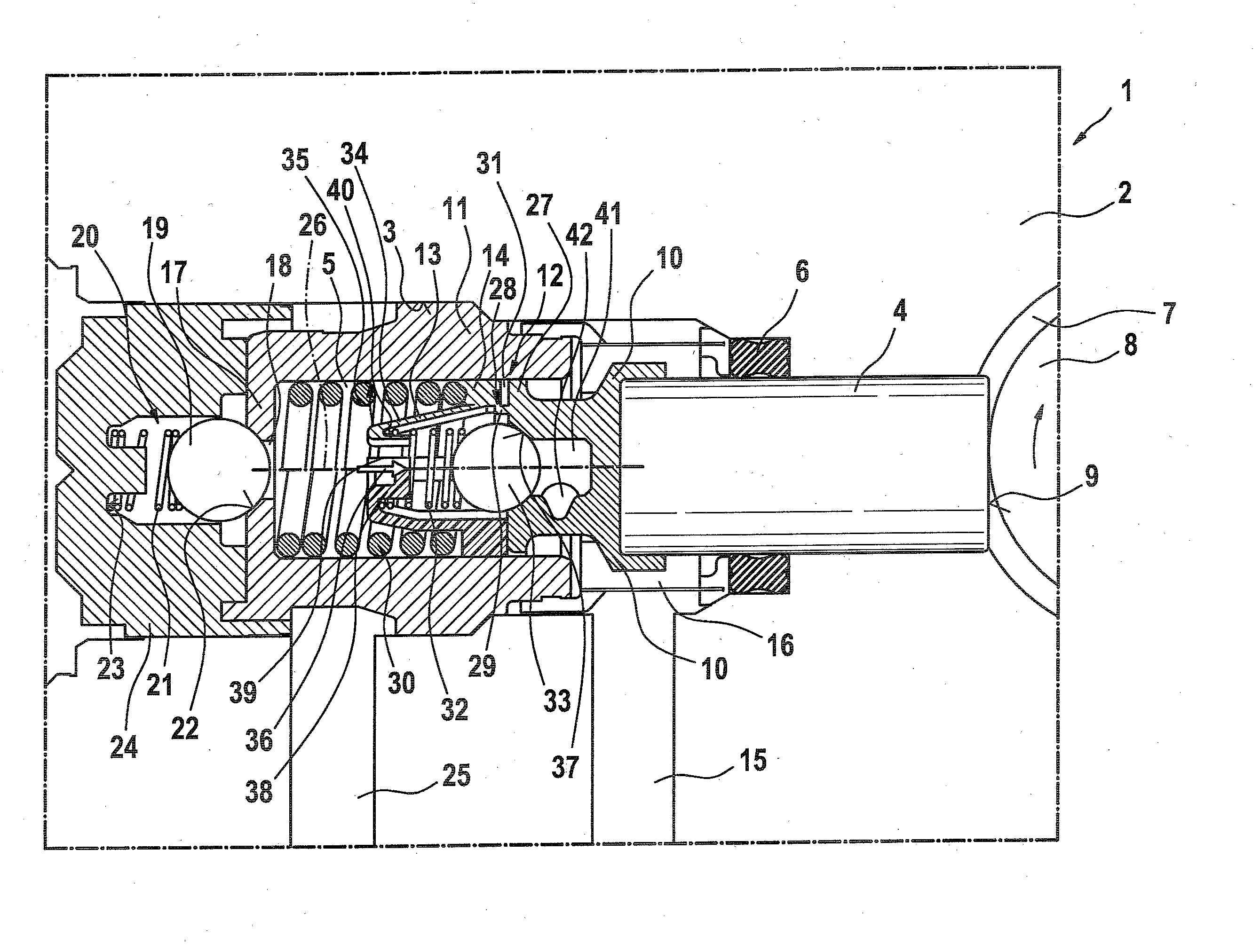
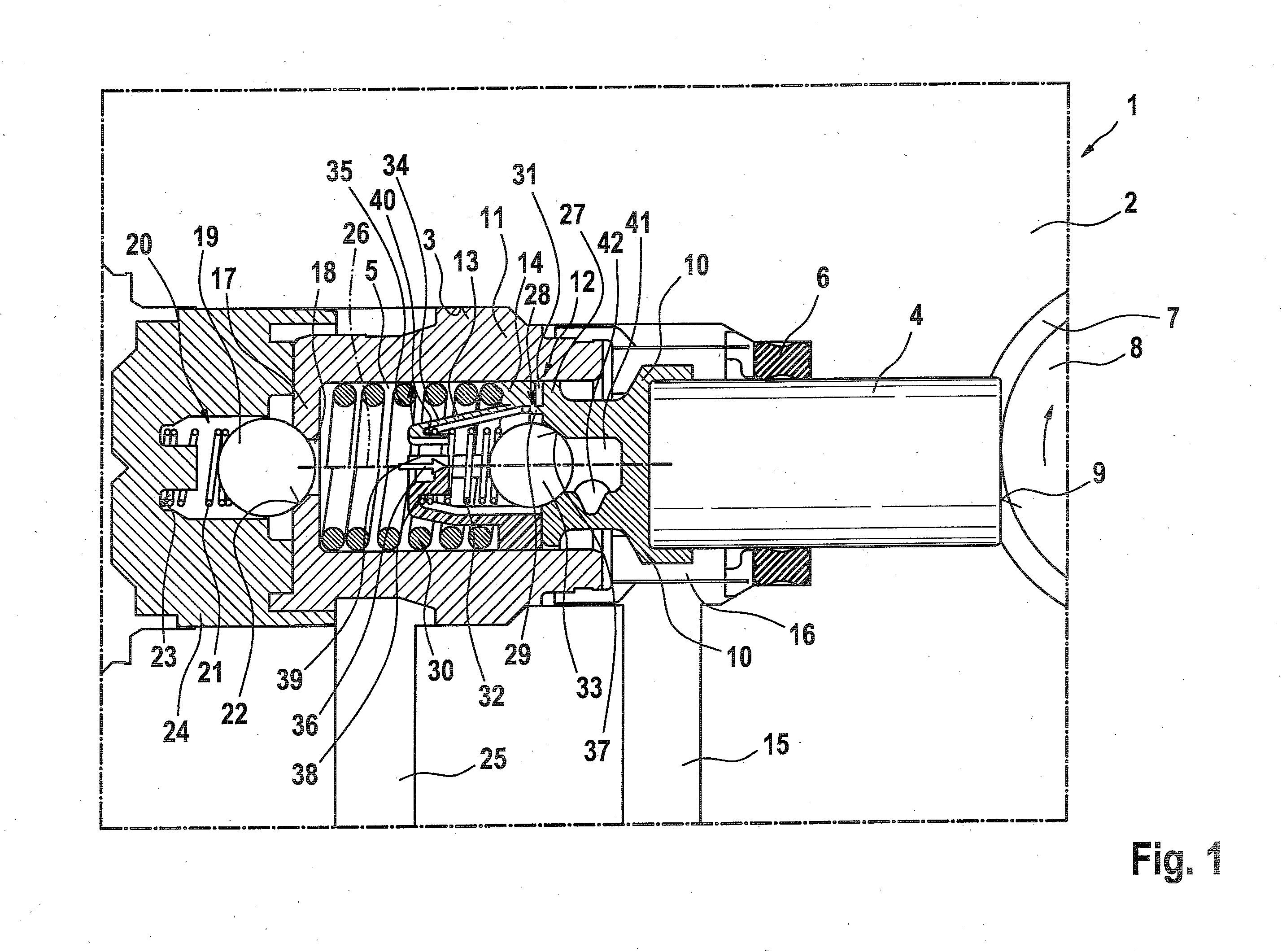
[0021]In the sole drawing, FIG. 1, a piston pump 1 is shown. It is disposed in a hydraulic block 2, in which besides the piston pump 1, other components, not shown, of a hydraulic vehicle brake system that has traction control, such as solenoid valves, check valves and hydraulic reservoirs, are accommodated and interconnected hydraulically with one another. The hydraulic block 2 forms a pump housing of the piston pump 1. A multiply-stepped pump bore 3 is made in this hydraulic block 2.

[0022]The piston pump 1 has a pump piston 4, whose end remote from a positive displacement chamber 5 is sealed off by an annular seal 6 from an eccentric chamber 7. In the eccentric chamber 7, an eccentric element 8 is driven rotatably about an axis of rotation that extends perpendicular to the longitudinal direction of the pump piston 4, and the pump piston 4 rests with its face end 9, remote from the positive displacement chamber 5, on the circumference of the eccentric element 8, which drives the pu...


PUM

PropertyMeasurementUnit
breaking pointaaaaaaaaaa
plasticaaaaaaaaaa
pressureaaaaaaaaaa

Abstract

The invention relates to a one-piece plastic element having an inlet valve cover and an inlet valve seat element for an inlet valve of a piston pump of a hydraulic brake system of a motor vehicle. The inlet valve is designed as a check valve, and the inlet valve cover and the inlet valve seat element are connected to each other by a designed fracture point. The invention further relates to a piston pump having an inlet valve cover and inlet valve seat element made of a one-piece plastic element. The invention further relates to a method for assembling the inlet valve designed as a check valve.

Description

PRIOR ART[0001]The invention relates to a one-piece plastic element as defined by claim 1, to a piston pump for a hydraulic brake system as defined generically by the preamble to claim 8, and to an assembly method as defined by claim 10.[0002]Piston pumps are used in hydraulic brake systems of motor vehicles and are often called return feed pumps. In a traction control mode, they serve to lower or raise the brake pressure in the wheel brake cylinders selectively so as to be able to regulate the brake pressure in the wheel brake cylinders.[0003]German Patent Disclosure DE 197 327 70 A1 shows a piston pump with an inlet valve embodied as a check valve; the inlet valve has a cup-shaped inlet valve cap embodied as a deep-drawn sheet-metal part. The inlet valve cap is urged by spring pressure in the axial direction by means of a restoring spring for a pump piston. A closing spring element and a closing body are disposed inside the inlet valve cap. The closing body is urged by spring pres...

Claims


Application Information

Patent Timeline
Patent Type & Authority Applications(United States)
IPC IPC(8): F04B37/00F16K27/00B23P15/00
CPCF04B1/0452Y10T29/49236B60T8/4031F04B53/10Y10T137/6086Y10T137/0497Y10T137/7927
Inventor HERMANN, HARALD
Owner ROBERT BOSCH GMBH
Why Eureka
Try Eureka