Tire vulcanization mold

a vulcanization mold and tire technology, applied in the field of tire vulcanization molds, can solve the problems of insufficient rubber filling, vulcanization failure, unnecessary air trapped, etc., and achieve the effect of ensuring efficient and stable ventilation, and reducing the number of vulcanization failures

Inactive Publication Date: 2012-08-30
THE YOKOHAMA RUBBER CO LTD
View PDF8 Cites 2 Cited by
  • Summary
  • Abstract
  • Description
  • Claims
  • Application Information

AI Technical Summary

Benefits of technology

[0008]An object of the present invention is to provide a tire vulcanization mold that can simplify machining associated with forming a venting mechanism and ensure stable ventilation.
[0011]With the former tire vulcanization mold according to the disclosed embodiments, machining associated with forming a ventilation groove in the tire molding surface such that it opens at the tire molding surface is simplified because the ventilation groove is rectangular in a plan view. Also, the blade has an upper end section, a contact section, and a communication section. The upper end section has a thickness smaller than a thickness of the ventilation groove. The contact section is below the upper end section and configured to contact both side faces of the ventilation groove when the blade is press fitted into the ventilation groove. The communication section communicates between the ventilation hole and a small gap formed between the ventilation groove and the upper end section. As a result, when the blade is fitted into the ventilation groove, the blade can be held by the contact section while securing a small gap between the blade and the ventilation groove across the entire length of the upper end section of the blade. Moreover, when a green tire is vulcanized, unnecessary air and gas can pass through the gap and the communication section and be vented to the exterior of the mold through the ventilation hole formed in the mold. By utilizing the ventilation groove formed in the tire molding surface such that it opens at the tire molding surface in an effective manner and making a surface area of the small gap as large as possible, efficient and stable ventilation can be ensured.
[0012]With the latter tire vulcanization mold, a ventilation groove is formed to be open at a tire molding surface and be rectangular in a plan view. A blade is press fitted and embedded in the ventilation groove, and the blade has a groove section formed in at least one side face that faces in a thickness direction of the blade. The groove section extends from an upper end to a lower end of the blade. As a result, machining associated with forming the blade and the ventilation groove is simplified. Since the shapes of the blade and the ventilation groove are simple, they can easily be machined to the designed shapes. Thus, since the small gap between the ventilation groove and the groove section can be formed according to design when the blade is embedded in the ventilation groove, stable ventilation can be ensured through the small gap and the ventilation hole.

Problems solved by technology

When a tire is vulcanized, unnecessary air can become trapped inside a tire vulcanization mold and gas can be generated by the vulcanization.
This air and gas can cause vulcanization failures such as insufficient rubber filling with respect to the tire being vulcanized.
However, since the small gap is formed by utilizing a difference between the thermal expansion coefficients (thermal contraction) of the blade and the mold main body, the size of the gap tends to vary and presents a disadvantage with respect to obtaining a stable ventilation efficiency.
More specifically, since the shape of the narrow hole provided in the tire molding surface is irregular and not simple in a plan view, the number of machining steps increases and the machining becomes complex.
Also, if the irregularly shaped narrow hole is not machined precisely, then stable ventilation cannot be ensured.
Moreover, when a green tire is vulcanized, unnecessary air and gas can pass through the gap and the communication section and be vented to the exterior of the mold through the ventilation hole formed in the mold.

Method used


Image

  • Tire vulcanization mold
  • Tire vulcanization mold
  • Tire vulcanization mold

Examples


Embodiment Construction

[0037]Selected embodiments of a tire vulcanization mold will now be explained with reference to the drawings. It will be apparent to those skilled in the art from this disclosure that the following descriptions of the embodiments are provided for illustration only and not for the purpose of limiting the invention as defined by the appended claims and their equivalents.

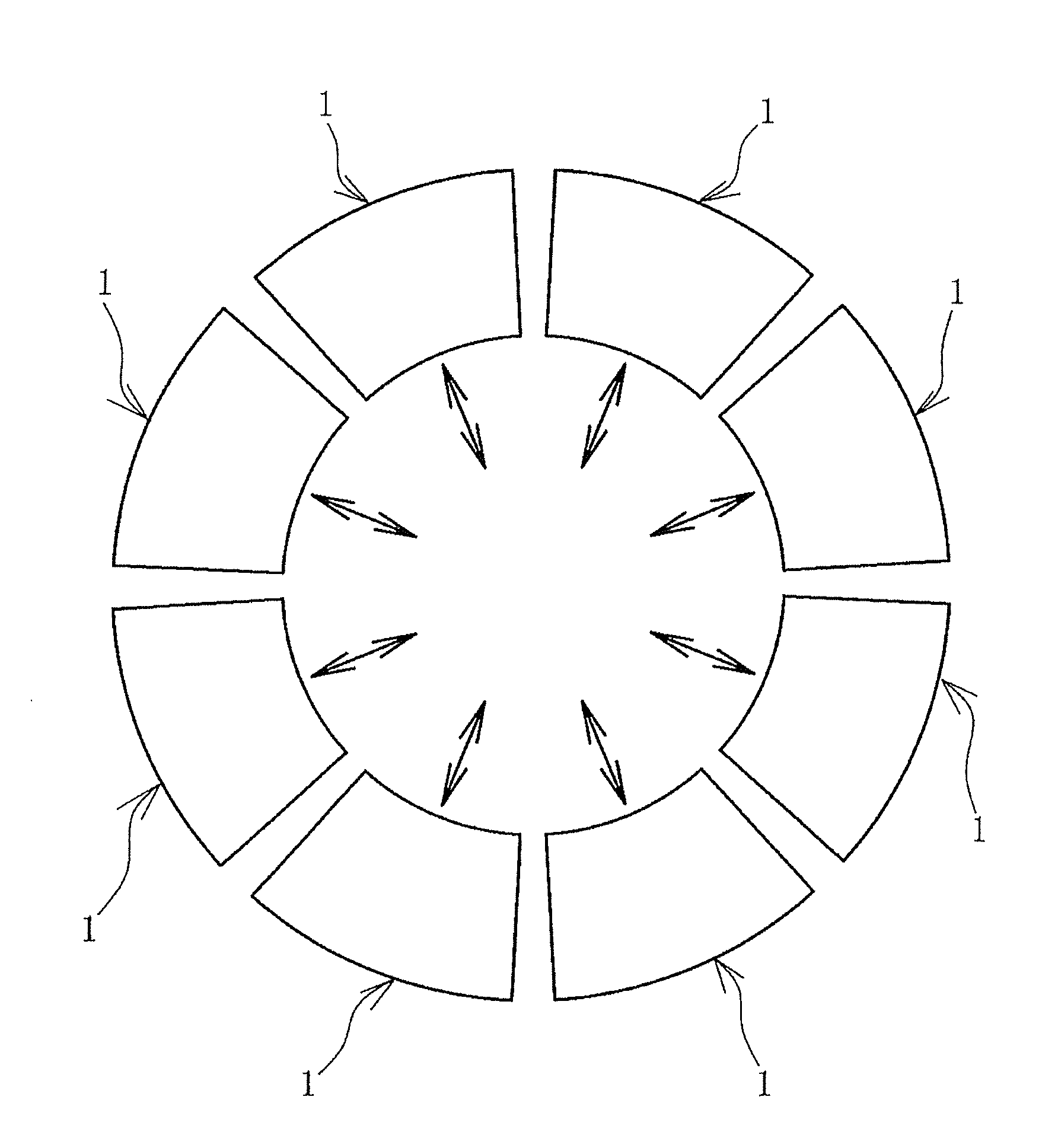
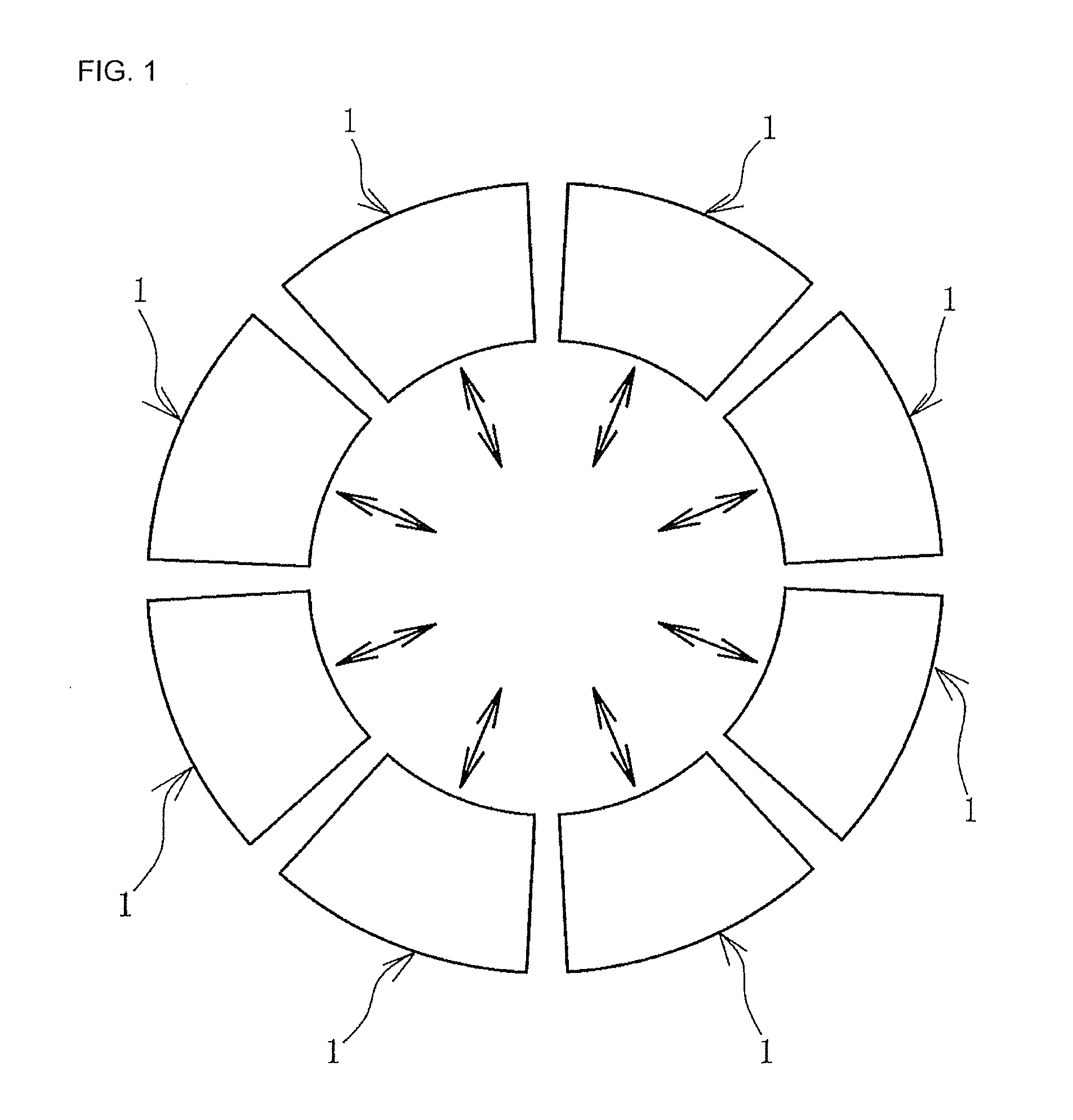
[0038]FIG. 1 shows a plurality of tire vulcanization molds 1 (hereinafter called “mold 1”) according to a disclosed embodiment. Each of the molds 1 in this example is a circular arc-shaped body and the molds 1 are attached together in an annular shape to form a sectional type mold. Each of the circular-arc shaped molds 1 toward and away from a center of the annular shape.

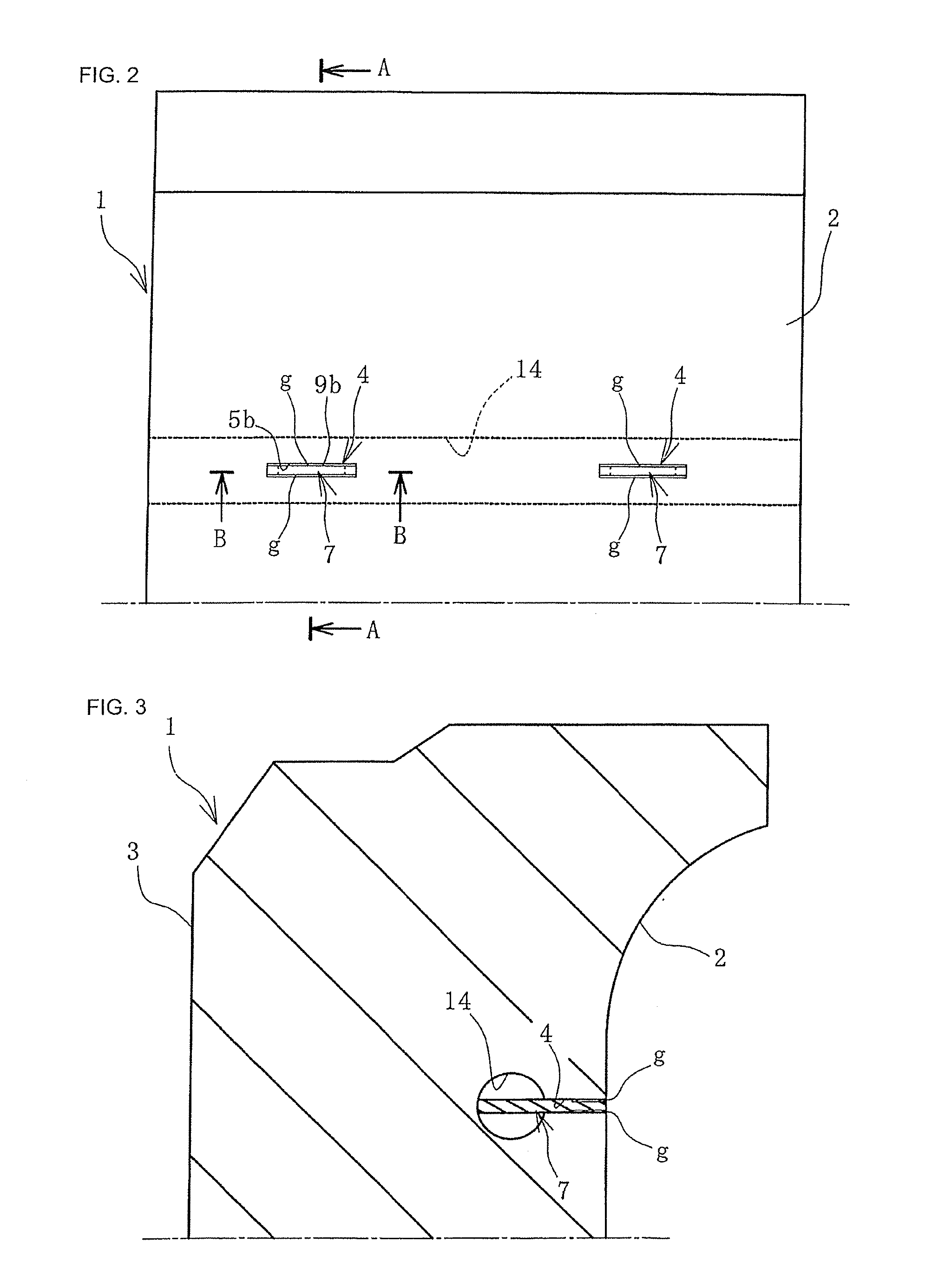
[0039]As shown in FIGS. 2 to 7, the molds 1 are made of aluminum or other material and have a tire molding surface 2 formed on an inner circumferential surface of the body 3 of the mold 1. A plurality of ventilation grooves 4 are formed in the tire mol...


PUM

PropertyMeasurementUnit
thicknessaaaaaaaaaa
thicknessaaaaaaaaaa
thicknessaaaaaaaaaa

Abstract

A tire vulcanization mold can be configured to provide stable ventilation. For example, a tire molding surface has a ventilation groove having a rectangular shape in plan view. A blade has upper end, contact and communication sections. The upper end section thickness is smaller than a groove thickness. The contact section below the upper end section contacts both thickness-direction-facing side faces of the groove. The communication section communicates between a ventilation hole, and a small gap is formed between the groove and the upper end section. Alternatively, the blade has a groove section formed in at least one side face that faces in a blade thickness direction and extends between upper and lower blade ends to form a small gap between the groove and groove section. Air and gas pass through the gap and the communication section and vent to an exterior of the mold through the ventilation hole.

Description

CROSS-REFERENCE TO RELATED APPLICATIONS[0001]This application claims priority to Japanese Patent Application No. 2011-037793, filed on Feb. 24, 2011, and Japanese Patent Application No. 2011-039887, filed on Feb. 25, 2011, the entire disclosures of Japanese Patent Application No. 2011-037793 and Japanese Patent Application No. 2011-039887 are hereby incorporated herein by reference.BACKGROUND[0002]1. Field of the Invention[0003]The present invention relates to a tire vulcanization mold. More particularly, the present invention relates to a tire vulcanization mold that can simplify a machining process associated with forming a venting mechanism and ensure stable ventilation.[0004]2. Background Information[0005]When a tire is vulcanized, unnecessary air can become trapped inside a tire vulcanization mold and gas can be generated by the vulcanization. This air and gas can cause vulcanization failures such as insufficient rubber filling with respect to the tire being vulcanized. Therefo...

Claims


Application Information

Patent Timeline
Patent Type & Authority Applications(United States)
IPC IPC(8): B29D30/08
CPCB29C33/10Y10S425/812B29D2030/0617B29D30/0606B29C35/02B29D30/08
Inventor MIYAZAKI, YUSAKU
Owner THE YOKOHAMA RUBBER CO LTD
Why Eureka
Try Eureka