
Method and apparatus for traffic management

Inactive Publication Date: 2012-08-30
IBM CORP
View PDF5 Cites 51 Cited by
  • Summary
  • Abstract
  • Description
  • Claims
  • Application Information

AI Technical Summary

Benefits of technology

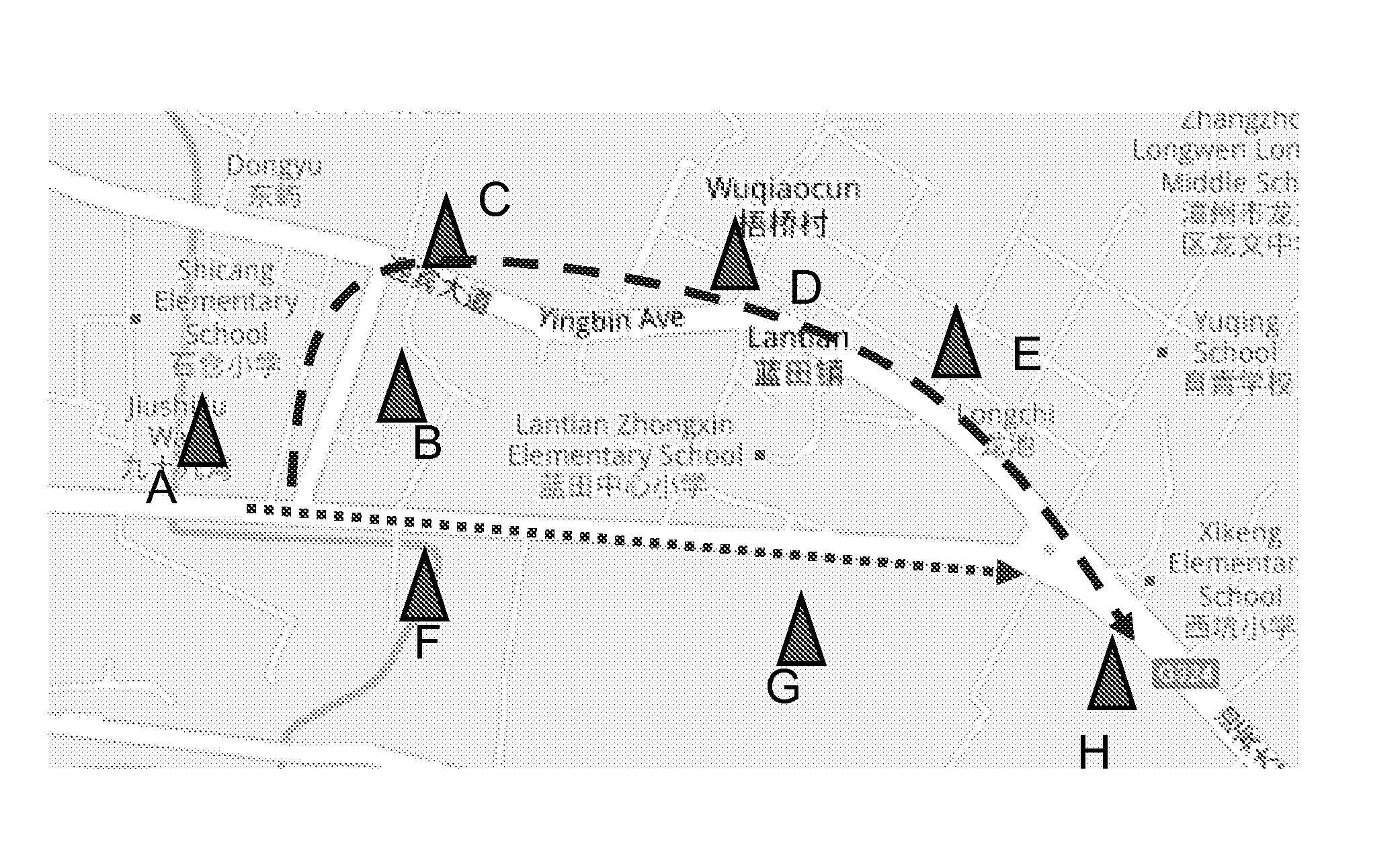
[0009]The present invention is proposed in view of the above technical problems, and its purpose is to provide a method and apparatus for determining real-time travel time of a vehicle on a road based on mobile communication network, which can accurately provide road traffic situation in real-time, cover all the roads and have low cost.

Problems solved by technology

However, this solution has not been applied to the vast suburban roads and inter-cities roads.
This is mainly because that: 1) the traffic sensor is expensive in both deployment and maintenance, and it is not suitable for suburban deployment; 2) the GPS floating car based solution highly depends on the number of floating cars on the monitored road, and in fact there is few floating cars running on the suburban and inter-cities roads.
However, such a solution depends on the number of the communication events happened on the monitored road, and it can not work if no communication events happen on the monitored road.
In addition, this solution is disadvantageous when the time difference between two continuous communication events is large, because the speed of the vehicle usually varies seriously during a long time interval.
Thus the solution can not evaluate the traffic situation of a road accurately.
By actively paging the phone of the mobile user, the position of the mobile user can be determined However, the function of active positioning will trigger signalling interaction between the base station and the mobile phone, which would cost a large amount of wireless resources.

Method used


Image

  • Method and apparatus for traffic management
  • Method and apparatus for traffic management
  • Method and apparatus for traffic management

Examples


Embodiment Construction

[0038]It is believed that the above and other objects, features and advantages of the present invention will be more apparent from the following detailed description of the embodiments in conjunction with accompany drawings.

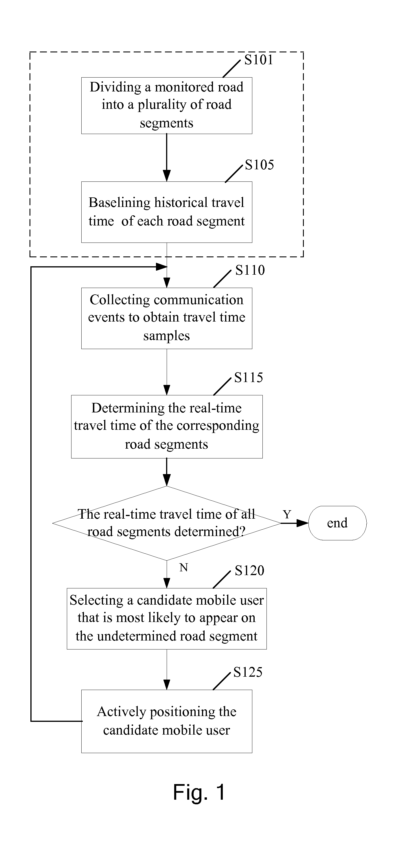
[0039]FIG. 1 is a flowchart of a method for determining real-time travel time of a road based on mobile communication network according to an embodiment of the invention. The embodiment will be described in detail in conjunction with the drawing.

[0040]It is well known that the mobile communication network consists of mobile terminals, base stations, and mobile switching centers etc. The base station may be an omni-directional base station which covers one cell, or a direction-oriented base station which covers many cells, e.g., three cells. When a communication event happens to the mobile terminal, for example, the mobile terminal enters into a new cell for position update, sends / receives a short message, initiates / receives a call, or performs handover during a s...


PUM


Abstract

A method for determining travel time of a vehicle on a road, wherein the vehicle is operable within a mobile communication network, comprising: collecting historical communication events of a mobile user in order to obtain travel samples, wherein the historical communication events indicate when the mobile user travelled along a monitored road; determining a cell handover sequence from the historical communication events; determining from the cell handover sequence, one of more road segments of the monitored road; determining the travel time of the one or more road segments according to the travel time samples; selecting, for an undetermined road segment of the monitored road for which the real-time travel time is not determined from the collected historical communication events, a candidate mobile user that is most likely to appear on the undetermined road segment; actively positioning the candidate mobile user to obtain positioning information; and returning to the step of collecting communication events of a mobile user currently on a monitored road with the active positioning as one communication event for the candidate mobile user, to determine the real-time travel time of the undetermined road segment.

Description

TECHNICAL FIELD[0001]The present invention relates to the field of road traffic management and mobile communication technology. In particular, the invention relates to the technology of monitoring road traffic by determining the real-time travel time of a vehicle on a road based on a mobile communication network.BACKGROUND OF THE INVENTION[0002]Road traffic monitoring is an important topic in road traffic management and navigation system. The traffic monitoring may be used to generate basic information for the road traffic, such as average speed of a vehicle, travel time of a road, road congestion degree, and incident position etc. By providing real-time basic information, the navigation system can learn the road traffic situation in time and reasonably arrange driving trajectories for the vehicles, thereby effectively reducing the congestion and avoiding collisions.[0003]Common solutions for monitoring road traffic based on traffic sensors (such as inductive loop detectors) and GPS...

Claims


Application Information

Patent Timeline
IPC IPC(8): G08G1/00H04W4/029
CPCH04W4/026H04W4/029H04W4/027G08G1/012G08G1/0129G08G1/0141G08G1/0133H04W64/00G08G1/01G08G1/0104
Inventor SHANG, WEI XIONGWANG, HUA YONGXIANG, ZHEYING, CHUNZHOU, JIN Z.ZHU, YAN FENG
Owner IBM CORP
Learn More