Controllable pneumatic brake booster and method for operating it

Inactive Publication Date: 2012-09-06
ROBERT BOSCH GMBH
View PDF1 Cites 5 Cited by
  • Summary
  • Abstract
  • Description
  • Claims
  • Application Information

AI Technical Summary

Benefits of technology

[0019]In the second operating mode it is provided that the supporting force of the brake booster is set only by the actuation of the main control valve. For this purpose, it is provided that the disconnecting valve as well as the control valve of the adjusting device not have current applied to them. In this way, the brake booster is able to be operated in the usual manner, which represents a fallback level in the case of current failure or a defect in the adjusting device. According to the additional specific embodiment, the third interrupting element of the adjusting device, that is, the valve which connects the adjusting device to the second chamber and/or the vacuum source, for deaerating the first chamber, is also closed in the currentless

Problems solved by technology

If this main control valve is suspended by interrupting the pneumatic connection, it is no longer able to contribute to the setting.
In this way, the brake

Method used


Image

  • Controllable pneumatic brake booster and method for operating it
  • Controllable pneumatic brake booster and method for operating it
  • Controllable pneumatic brake booster and method for operating it

Examples


Example

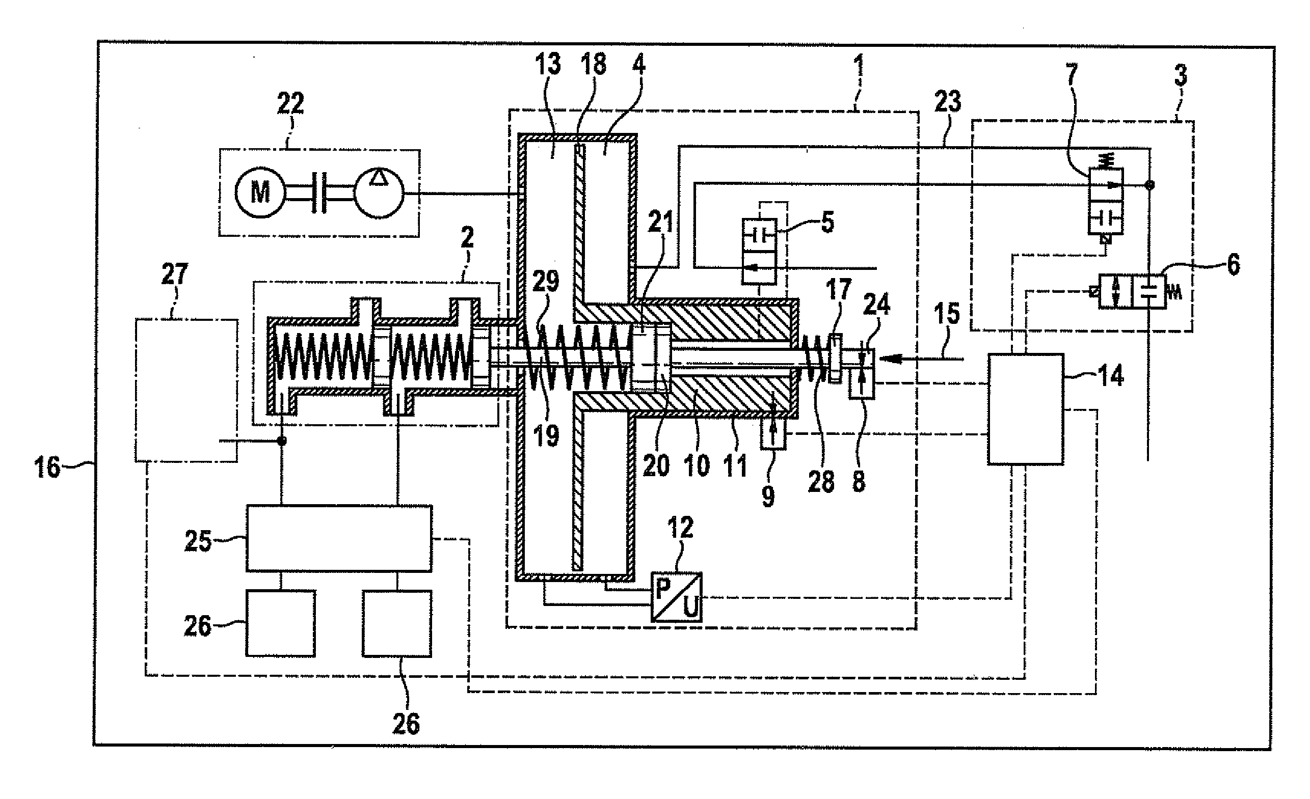
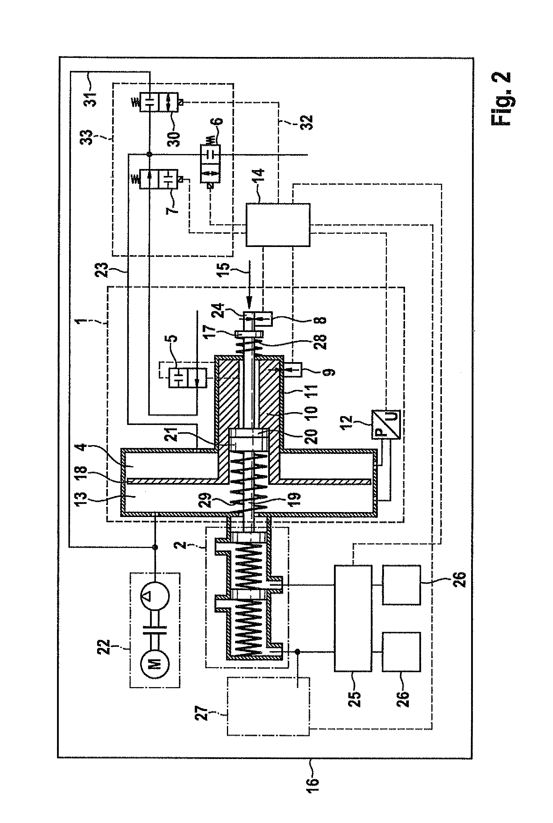
[0046]Similarly, it is possible, in the second specific embodiment, to ensure the protection from leakage of main control valve 5 or of control valve 6 via valve 30 and line 31. However, in that case, valve 30 has to be controlled by the control unit, since valve 30 is a currentless closed valve. The connection from the first chamber to vacuum supply 22 goes via line 23.

[0047]In general, a connection of main control valve 5 and of control valve 6 to vacuum supply 22 is possible both via valve 30 and valve 34, as well as via both valves at the same time.

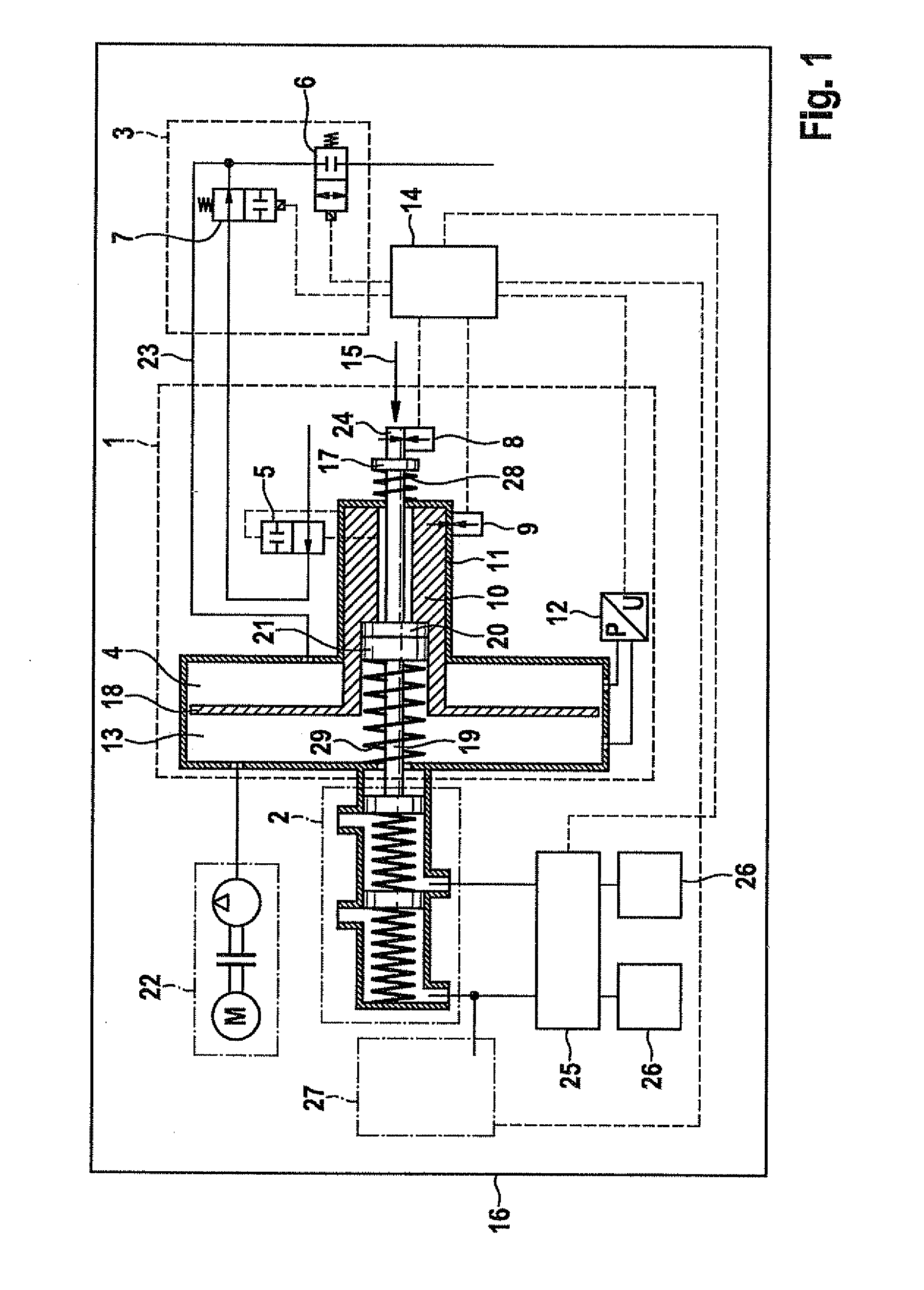
[0048]Because of the possibility of setting the supporting force of the brake booster via adjusting device 3, the brake booster 1 may be used in an overall brake system which, besides the hydraulic brake system includes an additional brake system such as a regenerative brake subsystem. When the proportion of the regenerative brake subsystem of the overall braking effect changes, the braking effect of the hydraulic brake system has to ...


PUM


Abstract

A vacuum brake booster which applies a supporting force to a main cylinder, as well as a method for its operation are described. The supporting force of the vacuum brake booster is able to be set via an adjusting device as well as via a main control valve. Consequently, the brake booster is operable in two operating modes, in a first operating mode, the supporting force being set by the adjusting device, and in a second operating mode, by the main control valve. Among other things, the brake booster is able to be used in brake systems in which the braking effect of a hydraulic and an additional brake system are combined, the braking effect of the hydraulic brake system having to be adapted to that of the additional brake system, for instance, in the case of regenerative brake systems of an electric or an hybrid vehicle.

Description

BACKGROUND INFORMATION[0001]In brake systems of a vehicle, for the deceleration of the vehicle by the vehicle's driver, pressure is built up in a brake circuit via a main cylinder. To support the driver, a brake booster is able to apply an additional supporting force, if necessary. One possible specific embodiment of such a brake booster is a vacuum brake booster, as is described, for instance, in ‘Kraftfahrtechnisches Taschenbuch’ (Automotive Handbook) (25th edition, BOSCH, Vieweg Verlag ISBN 3528238763, pages 805806). An active pneumatic brake booster is also described in ‘Handbuch Fahrerassistenzsysteme’ (Handbook of Driver Assistance Systems) (2009, Vieweg+Teubner Verlag ISBN 9783834802873). This brake booster is electrically controllable, independently of the driver. In such a brake booster, the poppet valve is operated using an electrically operated magnetic drive.SUMMARY[0002]The present invention relates to a vacuum brake booster and a method for operating the vacuum brake b...

Claims


Application Information

Patent Timeline
IPC IPC(8): F17D3/00F15B13/04
CPCB60T13/57Y10T137/0318
Inventor KOLARSKY, JENS
Owner ROBERT BOSCH GMBH
Why Eureka
Try Eureka