Power control device, power control method, and power supply system

a technology of power control device and power supply system, which is applied in the direction of electrochemical generators, instruments, transportation and packaging, etc., can solve the problems of deteriorating the entire storage battery, and increasing the load of remaining storage batteries, so as to reduce the deterioration of storage batteries and stable power

Active Publication Date: 2012-09-06
PANASONIC INTELLECTUAL PROPERTY MANAGEMENT CO LTD
View PDF2 Cites 60 Cited by
  • Summary
  • Abstract
  • Description
  • Claims
  • Application Information

AI Technical Summary

Benefits of technology

[0018]As described above, the present invention can provide a power control device...

Problems solved by technology

For example, when one of a plurality of storage batteries becomes unusable, the remaining usable storage batteries tend to have an increased load.
Consequently, the r...

Method used


Image

  • Power control device, power control method, and power supply system
  • Power control device, power control method, and power supply system
  • Power control device, power control method, and power supply system

Examples


embodiment 1

[0055]Hereinafter, a power control device according to Embodiment 1 of the present invention is described with reference to the drawings.

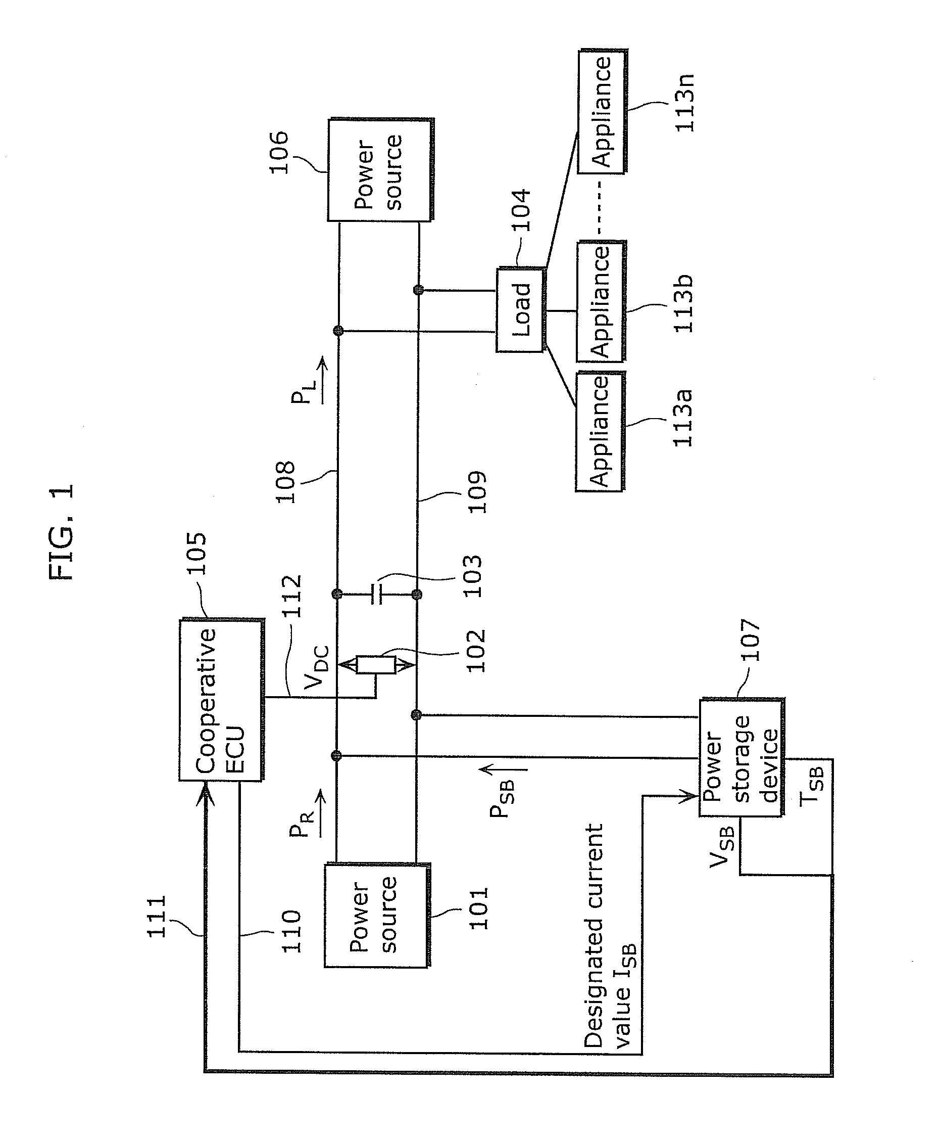
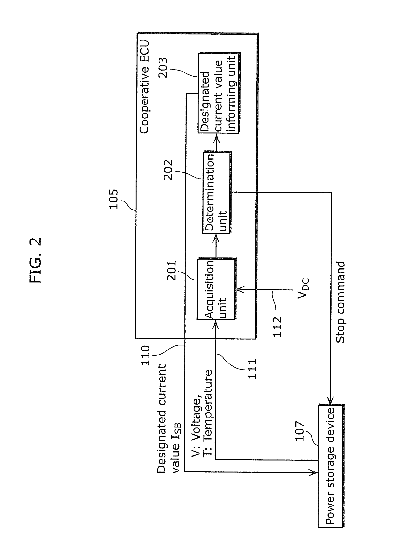
[0056]FIG. 1 is a system configuration diagram illustrating a power supply system which includes the power control device according to the present embodiment. A power control device is also referred to as a cooperative ECU. Therefore, the cooperative ECU in the following description corresponds to the power control device in the claims.

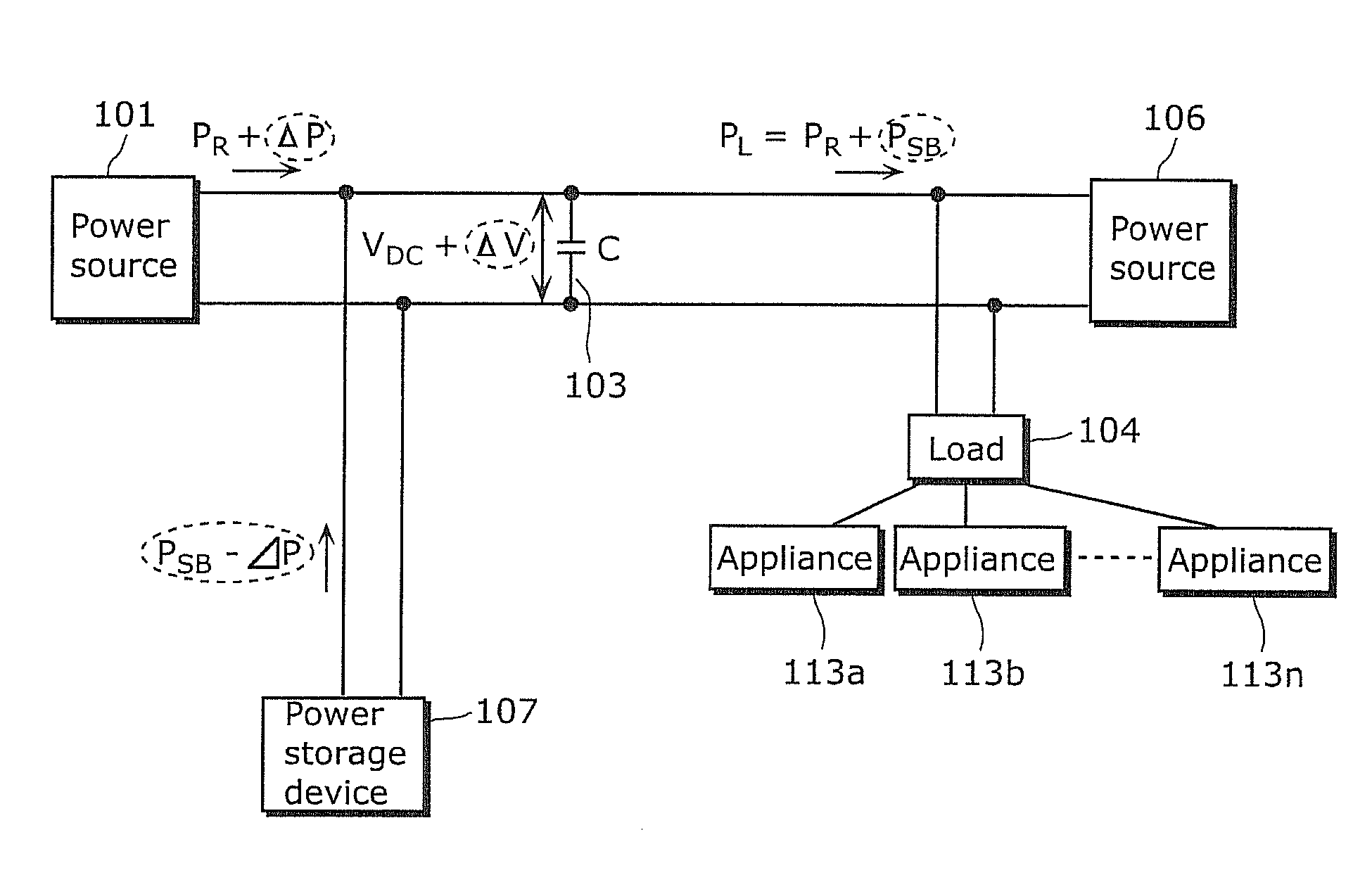
[0057]In FIG. 1, the power supply system according to the present embodiment includes a power source 101, a power source 106, a capacitor 103, a load 104, a cooperative ECU 105, and a power storage device 107.

[0058]The power source 101, the power source 106, the capacitor 103, the load 104, and the power storage device 107 are connected to each other via a positive polarity power line 108 and a negative polarity power line 109. The load 104 is connected to n pieces of appliances (n≧11) 113 (hereinafter, an appliance ...

embodiment 2

[0142]In the cooperative ECU 105 according to Embodiment 1 controls charging and discharging performed by a single power storage device 107. On the other hand, the cooperative ECU according to Embodiment 2 controls charging and discharging performed by a plurality of power storage devices on the storage batteries provided in each power storage device. In this case, a variation in the capacitors of the storage batteries occurs when the remaining capacity of each storage battery is independently controlled. Consequently, a variation in the life spans of the storage batteries occurs. In addition, the life of the entire power storage devices is reduced.

[0143]Thus, when the fluctuation component of the DC link voltage VDC is compensated, the cooperative ECU according to Embodiment 2 controls charging and discharge of each power storage device so as to make the remaining capacities of the storage batteries uniform. Accordingly, stable power can be supplied to the load 104 while a reductio...

embodiment 3

[0178]In Embodiment 1 and Embodiment 2, the case has been described where the power supplied to the load is DC.

[0179]In Embodiment 3, a case is described where the power supplied to the load is AC.

[0180]Hereinafter, the cooperative ECU used in Embodiment 3 of the present invention is described.

[0181]FIG. 18 is a system configuration diagram illustrating a power supply system including a cooperative ECU1605 as a power control device according to the present embodiment. In FIG. 18, the power generated by a power generation system using renewable energy is supplied by a power source 1601 in the present embodiment.

[0182]In the present aspect, the power source 1601 generated by a solar photovoltaic power generation system is described as an example of renewable energy, however, as another example of renewable energy, a power generation system which uses energy such as wind power, solar heat, geothermal heat, ocean current, wave power, or tidal power may be applied. In the present embodim...


PUM


Abstract

The control device (105) includes: an acquisition unit (201) which acquires voltage information indicating a voltage applied to a capacitor provided between a power generation unit and a load via first and second power supply lines, and deterioration information indicating a state of deterioration of a storage battery connected to the power generation unit; a determination unit (202) which compares the acquired voltage information with a reference voltage so as to detect a fluctuation of the voltage, and determines power to be outputted so as to suppress the fluctuation; and an informing unit (203) which informs the storage battery of a current value corresponding to the power to be outputted, wherein the determination unit (202) detects a state of deterioration of the storage battery using the deterioration information, and determines power to be outputted in accordance with the state of deterioration.

Description

TECHNICAL FIELD[0001]The present invention relates to a power control device which supplies stable power to a load.BACKGROUND ART[0002]In recent years, power supply systems using renewable energy such as sunlight and wind power have been researched. Such power supply systems each generate power using renewable energy such as sunlight and wind power in a facility, for example, a building, a factory, or a household. In each facility, there are installed one or more storage batteries which store generated power, and a cooperative ECU (Electronic Control Unit) which controls charging and discharging of the storage batteries. Various electric appliances such as a refrigerator, a television, and an electric vehicle installed in each facility can be operated utilizing the power stored in a plurality of storage batteries.[0003]However, in a power supply system, an increased variation in the frequencies of charging and discharging to and from the storage batteries causes a variation in the p...

Claims


Application Information

Patent Timeline
IPC IPC(8): H02J7/00
CPCG01R31/3679H02J3/32H01M10/443H01M10/441H02J7/35Y02P90/50G01R31/392Y02E60/10
Inventor KINJO, TATSUTOKAJI, MITSURUKUDOH, TAKAHIRO
Owner PANASONIC INTELLECTUAL PROPERTY MANAGEMENT CO LTD
Why Eureka
Try Eureka