
Terminal device for transmitting a power headroom report in a multi-carrier communication system, and method for same

a communication system and terminal device technology, applied in power management, wireless commuication services, orthogonal multiplexes, etc., can solve the problems of not yet disclosed power headroom report performance of the ue, achieve effective transmission minimize the number of generable transmission power limitation situations, and minimize the effect of power headroom repor

Active Publication Date: 2012-09-06
LG ELECTRONICS INC
View PDF6 Cites 58 Cited by
  • Summary
  • Abstract
  • Description
  • Claims
  • Application Information

AI Technical Summary

Benefits of technology

[0026]As is apparent from the above description, exemplary embodiments of the present invention have the following effects. A UE apparatus can effectively transmit an uplink power headroom report (PHR) even in a multi-carrier communication system.
[0027]If there are many multi-carrier systems or many uplink data and control channels to be simultaneously transmitted, a UE can minimize the number of generable transmission power limitation situations, such that it can effectively transmit a power headroom report (PHR).
[0028]The eNode B (eNB) can efficiently establish a UE MCS level or the like using a power headroom reported by a UE, and can more precisely control the UE, resulting in implementation of efficient scheduling.
[0029]It will be appreciated by persons skilled in the art that the effects that can be achieved with the present invention are not limited to what has been particularly described hereinabove and other advantages of the present invention will be more clearly understood from the following detailed description taken in conjunction with the accompanying drawings.

Problems solved by technology

However, the above-mentioned method for performing the power headroom report (PHR) by the UE has not yet been disclosed.

Method used


Image

  • Terminal device for transmitting a power headroom report in a multi-carrier communication system, and method for same
  • Terminal device for transmitting a power headroom report in a multi-carrier communication system, and method for same
  • Terminal device for transmitting a power headroom report in a multi-carrier communication system, and method for same

Examples


Embodiment Construction

Technical Problem

[0010]Accordingly, the present invention is directed to a UE for transmitting a power headroom report (PHR) in a multi-carrier support communication system and an apparatus for the same that substantially obviate one or more problems due to limitations and disadvantages of the related art. An object of the present invention is to provide a method for transmitting a power headroom report (PHR) by a user equipment (UE) in a multi-carrier support communication system.

[0011]Another object of the present invention is to provide a UE apparatus for enabling a UE to transmit a power headroom report (PHR) in a multi-carrier support communication system.

[0012]It is to be understood that technical objects to be achieved by the present invention are not limited to the aforementioned technical objects and other technical objects which are not mentioned herein will be apparent from the following description to one of ordinary skill in the art to which the present invention pertai...


PUM


Abstract

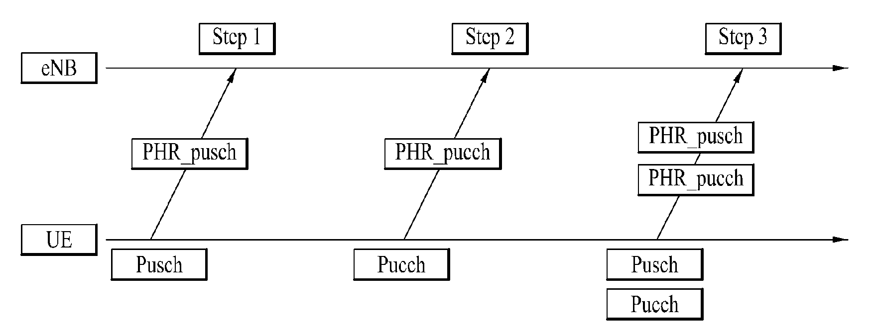
Disclosed is a terminal device for transmitting a power headroom report (PHR) in a multi-carrier communication system, and a method for same. The terminal device for transmitting a power headroom report (PHR) in a multi-carrier communication system comprises a transmitter and a processor. The transmitter transmits, to a base station, a power headroom report for one or more active component carriers allocated to user equipment from among multiple carriers. The processor controls the transmitter such that the transmitter transmits the power headroom report including a first type of power headroom information calculated using the power value of a physical uplink shared channel (PUSCH) of the main component carrier among the active component carriers, and a second type of power headroom information calculated using the power value of the PUSCH and the power value of a physical uplink control channel (PUCCH) of the main component carrier.

Description

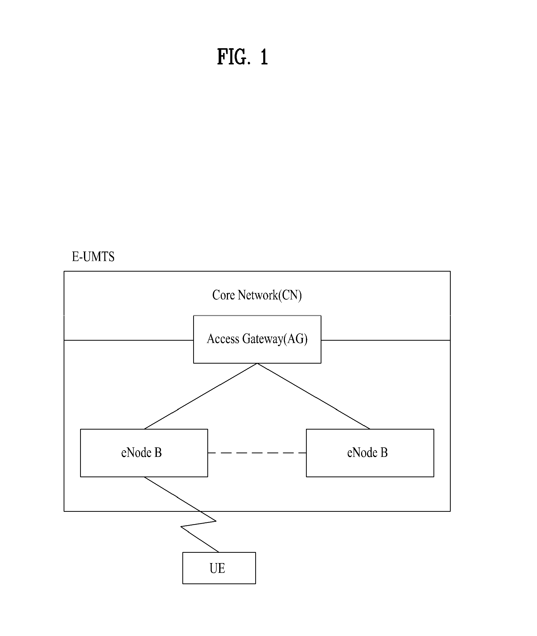
FIELD OF THE INVENTION[0001]The present invention relates to a method and apparatus for transmitting a power headroom report (PHR).BACKGROUND ART[0002]As a representative example of a wireless communication system of the present invention, 3rd Generation Partnership Project Long Term Evolution (3GPP LTE) and LTE-Advanced (LTE-A) communication systems will hereinafter be described in detail.[0003]FIG. 1 is a conceptual diagram illustrating an Evolved Universal Mobile Telecommunications System (E-UMTS) network structure as an exemplary mobile communication system. In particular, the Enhanced Universal Mobile Telecommunications System (E-UMTS) has evolved from a legacy UMTS system, and basic standardization thereof is now being conducted by the 3rd Generation Partnership Project (3GPP). E-UMTS may also be referred to as Long Term Evolution (LTE). For details of the technical specifications of UMTS and E-UMTS, refer to Release 7 and Release 8 of “3rd Generation Partnership Project; Tech...

Claims


Application Information

Patent Timeline
IPC IPC(8): H04W52/16
CPCH04W52/367H04W72/042H04W52/365H04W52/34H04J11/0036H04L5/0007H04W88/02H04W72/0453H04W72/21H04W72/23H04L5/0053H04L1/1812H04W72/0473H04W72/12H04W88/08
Inventor KIM, DONG CHEOLMOON, SUNG HOCHO, HAN GYUCHUNG, JAE HOON
Owner LG ELECTRONICS INC
Learn More