Gas burner

a burner and gas technology, applied in the direction of burners, combustion types, combustion processes, etc., can solve the problems of increased manufacturing cost, difficulty in controlling premix burners, large number of parts, etc., and achieve the effect of reducing the number of manufacturing processes and reducing the manufacturing cos

Inactive Publication Date: 2012-09-06
KYUNGDONG NAVIEN
View PDF4 Cites 5 Cited by
  • Summary
  • Abstract
  • Description
  • Claims
  • Application Information

AI Technical Summary

Benefits of technology

[0012]According to the present invention, since it is unnecessary to weld the burner body and the side plate, the number of manufacturing processes is reduced, and thus the manufacturing cost is reduced. Further, since the welding is not required, it is possible to assemble the gas burner again when the gas burner is incorrectly assembled.

Problems solved by technology

However, the premix burner has difficulty in control because the range of an air ratio for stable combustion is narrow.
Most lean-rich burners are designed in the form of a dual gas pipe (in which one gas pipe is used for an air-rich mixture and the other gas pipe is used for a gas-rich mixture), and thus have a complicated structure and a large number of parts, which leads to an increase in manufacturing cost.
In this manner, when the burner body 10 and the side plates 20 are coupled by welding, the number of manufacturing processes is increased, and thus the cost of production is increased.

Method used


Image

  • Gas burner
  • Gas burner
  • Gas burner

Examples


Embodiment Construction

[0025]Hereinafter, the construction and operation of exemplary embodiments of the present invention will be described in detail with reference to the accompanying drawings.

[0026]FIG. 3 is a plan view showing a gas burner according to an embodiment of the present invention.

[0027]The gas burner 1 includes burner units 100 forming a flame, and first and second brackets 200a and 200b supporting opposite ends of the burner units 100.

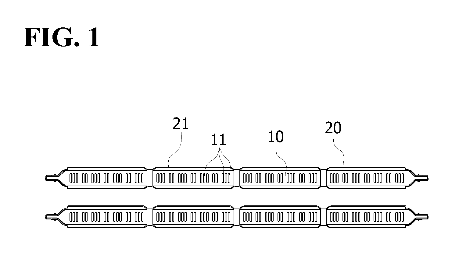
[0028]Each burner unit 100 has a structure in which a plurality of burner units 110, 120 and 130 are disposed in a row at regular intervals.

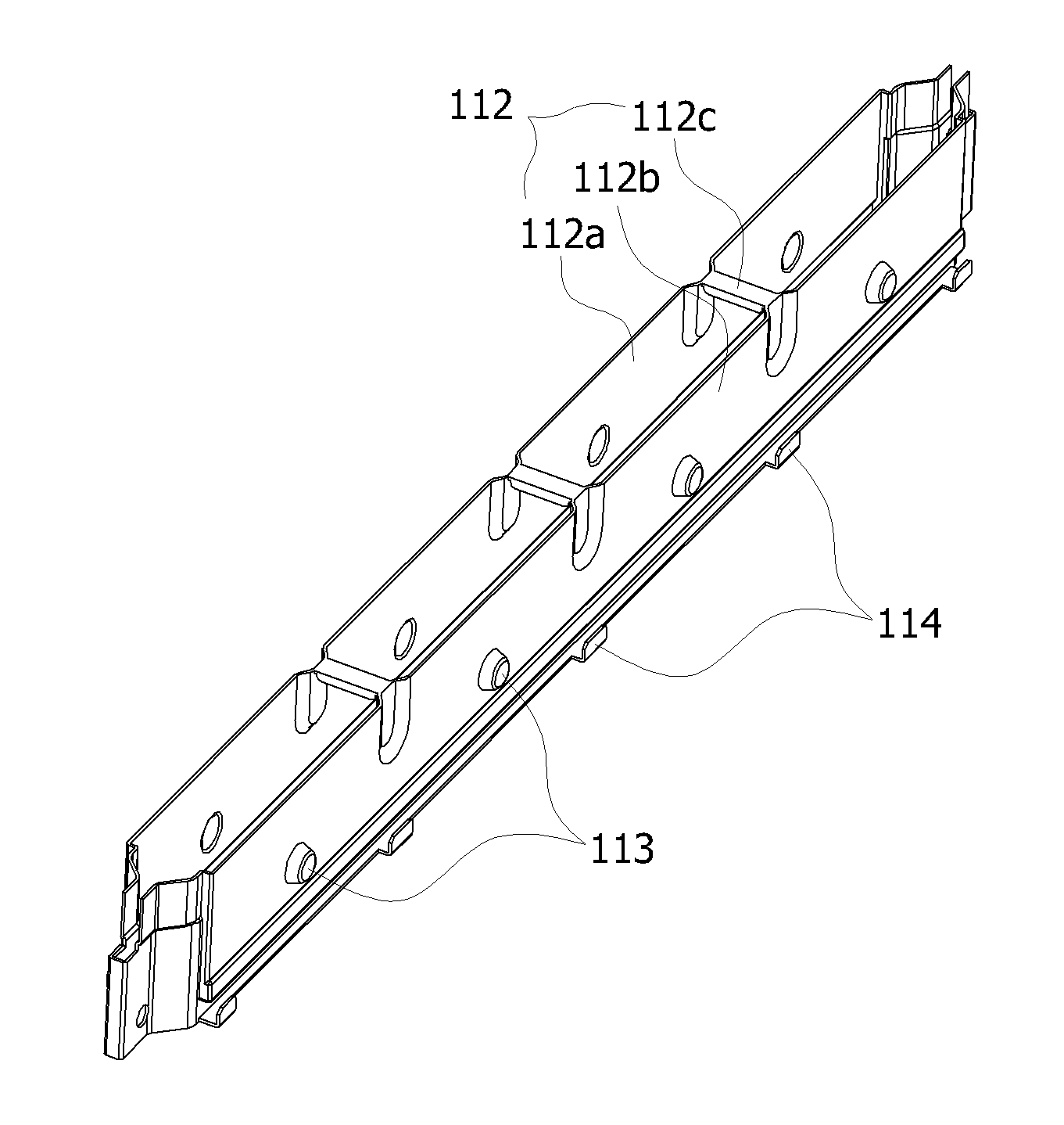
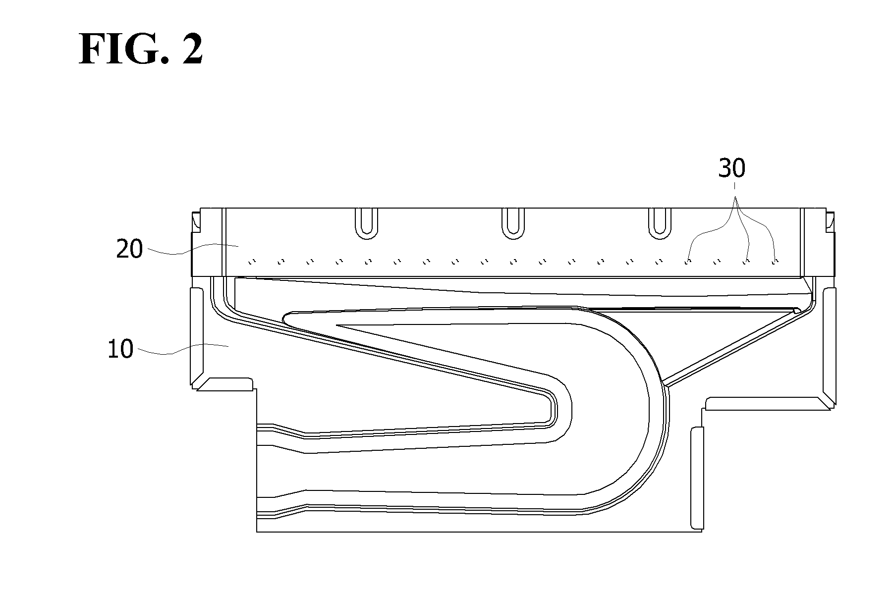
[0029]Opposite ends of each of the burner units 110, 120 and 130 have a shape in which a plurality of plates are bent so as to have a narrower width than a burner body, and are inserted into and fixed in grooves formed in the first and second brackets 200a and 200b.

[0030]FIG. 4 is a plan view showing a structure in which the burner units are of the present invention mutually supported.

[0031]Two of the burner units 110 an...


PUM


Abstract

The present invention relates to a gas burner in which a burner body and a side plate are assembled together without a welding process, to thereby simplify manufacturing procedures and reduce manufacturing costs. To accomplish this, the gas burner of the present invention includes a plurality of burner units (110), each of which has a burner body (111) with a main flame being formed at the top thereof, a side plate (112) which forms auxiliary flame holes (116) in the spaces between both side surfaces of the burner body (111) and the side plate (112), and a plurality of supports (113, 114) protruding from the side plate (112). Both ends of each of the burner units (110) are supported by first and second brackets (200a, 200b), respectively. The supports (113, 114) formed at the side plate (112) of the burner unit are brought into contact with and are supported by supports (123, 124) formed at a side plate (122) of an adjacent burner unit (120).

Description

TECHNICAL FIELD[0001]The present invention relates to a gas burner, and more particularly, to a gas burner in which a plurality of burner units for forming a flame are mutually supported, thereby making it possible to simplify manufacturing processes.BACKGROUND ART[0002]Most household gas boilers employ a semi Bunsen burner due to stable inflammability. This semi Bunsen burner mixes some air (primary air) supplied from a blower with gas fuel in advance and supplies the mixture to a combustion unit to form a flame. The semi Bunsen burner supplies the rest of the air (secondary air) supplied from the blower to a flame forming part, thereby inducing complete combustion.[0003]To prevent harmful emissions (e.g. CO) from being excessively discharged from such a burner, the output of the burner is generally required to be less than 2,000 kcal / h. In this case, when the output per burner unit is designed to be low, many burner units should be installed to meet the maximum output required fro...

Claims


Application Information

Patent Timeline
Patent Type & Authority Applications(United States)
IPC IPC(8): F23D14/04F23D14/46
CPCF23D14/10F23D14/045F23D14/04F23D14/46F24H9/18
Inventor MIN, MOUNG-GEEJOO, JAE-MYUNG
Owner KYUNGDONG NAVIEN
Why Eureka
Try Eureka