Ultrasound diagnostic apparatus and ultrasound image producing method

a diagnostic apparatus and ultrasound technology, applied in diagnostics, medical science, applications, etc., can solve problems such as the temperature inside the housing of the ultrasound probe, and achieve the effect of high image quality mode and easy knowing

Inactive Publication Date: 2012-09-06
FUJIFILM CORP
View PDF11 Cites 66 Cited by
  • Summary
  • Abstract
  • Description
  • Claims
  • Application Information

AI Technical Summary

Benefits of technology

[0009]The present invention has been made to solve the foregoing prior art problems and an object of the invention is to provide an ultrasound diagnostic apparatus capable of easily knowing how long more the

Problems solved by technology

Therefore, the heat generated in the transducer array may rai

Method used


Image

  • Ultrasound diagnostic apparatus and ultrasound image producing method
  • Ultrasound diagnostic apparatus and ultrasound image producing method
  • Ultrasound diagnostic apparatus and ultrasound image producing method

Examples


embodiment 1

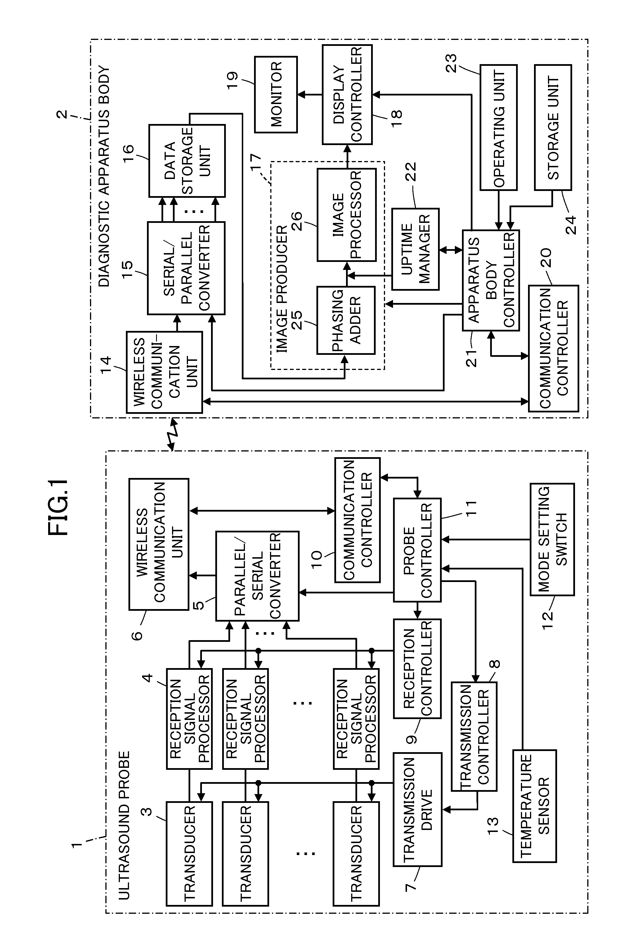
[0027]FIG. 1 shows the configuration of an ultrasound diagnostic apparatus according to Embodiment 1 of the invention. The ultrasound diagnostic apparatus comprises an ultrasound probe 1 and a diagnostic apparatus body 2 that is connected to the ultrasound probe 1 via wireless communication.

[0028]The ultrasound probe 1 comprises a plurality of ultrasound transducers 3 constituting a plurality of channels of a one-dimensional or two-dimensional transducer array, and the transducers 3 are connected to their corresponding reception signal processors 4, which in turn are connected to a wireless communication unit 6 via a parallel / serial converter 5. The transducers 3 are connected to a transmission controller 8 via a transmission drive 7, the reception signal processors 4 are connected to a reception controller 9, and the wireless communication unit 6 is connected to a communication controller 10. The parallel / serial converter 5, the transmission controller 8, the reception controller 9...

embodiment 2

[0074]FIG. 5 shows the configuration of an ultrasound probe 31 that may be used in the ultrasound diagnostic apparatus according to Embodiment 2. The ultrasound probe 31 is obtained by providing the ultrasound probe 1 of Embodiment 1 shown in FIG. 1 with a plurality of temperature sensors 13a to 13c instead of the temperature sensor 13.

[0075]The temperature sensors 13a to 13c are connected to the probe controller 11. These temperature sensors 13a to 13c are preferably disposed, for example, near the reception signal processors 4, near the transducer array (not shown), on the periphery of the battery, at the housing of the ultrasound probe 31 held by the operator or near a member where heat is expected to develop during the operation.

[0076]The temperature values detected by the temperature sensors 13a to 13c are wirelessly transmitted from the probe controller 11 to the diagnostic apparatus body 2 via the communication controller 10 and the wireless communication unit 6. The temperat...


PUM


Abstract

An ultrasound diagnostic apparatus comprises: an ultrasound probe which performs transmission and reception of ultrasonic beams using a transducer array according to a mode selected by an operator from a low image quality mode and a high image quality mode, and which processes reception signals outputted from the transducer array in reception signal processors to generate digital reception data; a diagnostic apparatus body for producing an ultrasound image based on the reception data transmitted from the ultrasound probe and displaying the produced ultrasound image on a monitor; a temperature detecting unit for detecting an internal temperature of the ultrasound probe, and an uptime manager for calculating an uptime in the high image quality mode based on the internal temperature of the ultrasound probe detected by the temperature detecting unit to display the calculated uptime on the monitor.

Description

BACKGROUND OF THE INVENTION[0001]The present invention relates to an ultrasound diagnostic apparatus and an ultrasound image producing method. The invention more particularly relates to an ultrasound diagnostic apparatus for making a diagnosis based on ultrasound images produced by transmitting and receiving ultrasonic waves from and in a transducer array of an ultrasound probe.[0002]Conventionally, ultrasound diagnostic apparatus using ultrasound images are employed in the medical field. In general, this type of ultrasound diagnostic apparatus comprises an ultrasound probe having a built-in transducer array and an apparatus body connected to the ultrasound probe. The ultrasound probe transmits ultrasonic waves toward a subject and receives ultrasonic echoes from the subject, and the apparatus body electrically processes the reception signals to generate an ultrasound image.[0003]In such ultrasound diagnostic apparatus, the transducer array transmits ultrasonic waves to generate hea...

Claims


Application Information

Patent Timeline
IPC IPC(8): A61B8/13
CPCA61B8/13A61B8/4472A61B8/546A61B8/467A61B8/461
Inventor KUDOH, YOSHIMITSU
Owner FUJIFILM CORP
Why Eureka
Try Eureka