Friction force microscope

a technology of friction force and microscope, which is applied in the field of friction force microscope, can solve the problems of difficult to use the apparatus in an application, the inability of the conventional friction force microscope to measure the absolute value of the friction force, and the inability to accurately correct the parameters of the cantilever, etc., and achieve the effect of measuring accurately

Active Publication Date: 2012-09-06
HITACHI HIGH TECH SCI CORP
View PDF36 Cites 7 Cited by
  • Summary
  • Abstract
  • Description
  • Claims
  • Application Information

AI Technical Summary

Benefits of technology

[0016]According to the friction force microscope of the present invention, as described above, after accurately measuring the torsional spring constant of the cantilever, the probe is set to be in contact with the sample to scan the sample, and hence the friction force between the probe and the sample can be measured accurately from a torsional displacement of the cantilever generated by the friction force between the probe and the sample.

Problems solved by technology

However, a conventional friction force microscope can easily measure a relative distribution of the friction force between the probe and the sample surface in the measurement range, but it is difficult for the conventional friction force microscope to measure an absolute value of the friction force.
Therefore, it is difficult to use the apparatus in an application where friction forces of a plurality of sample are compared with each other by using a plurality of cantilevers.
Here, there is a problem as a variation of characteristics of the cantilever, which are parameters necessary for calculating the friction force from the measured torsional displacement signal, including (i) a torsional spring constant of the cantilever, (ii) sensitivity of a torsion signal of the cantilever, and (iii) a height of the cantilever probe.
However, the methods described above for correcting parameters of the cantilever have the following problems.
(i) It is difficult to accurately measure a thickness as a dimension of the cantilever, and because a spring constant in the torsional direction is proportional to the cube of the thickness, an original measuring error is enlarged.
As a result, it is difficult to calculate an accurate torsional spring constant value.
(iii) The probe tip of the cantilever is too small to observe by an optical microscope so that measurement is difficult.
However, the rotation center of the cantilever torsion cannot be identified only by observing externally using a microscope or the like, and there is no means for determining from which part the length to the probe tip should be measured.

Method used


Image

  • Friction force microscope
  • Friction force microscope
  • Friction force microscope

Examples


Embodiment Construction

[0020]A friction force microscope according to an embodiment of the present invention is described.

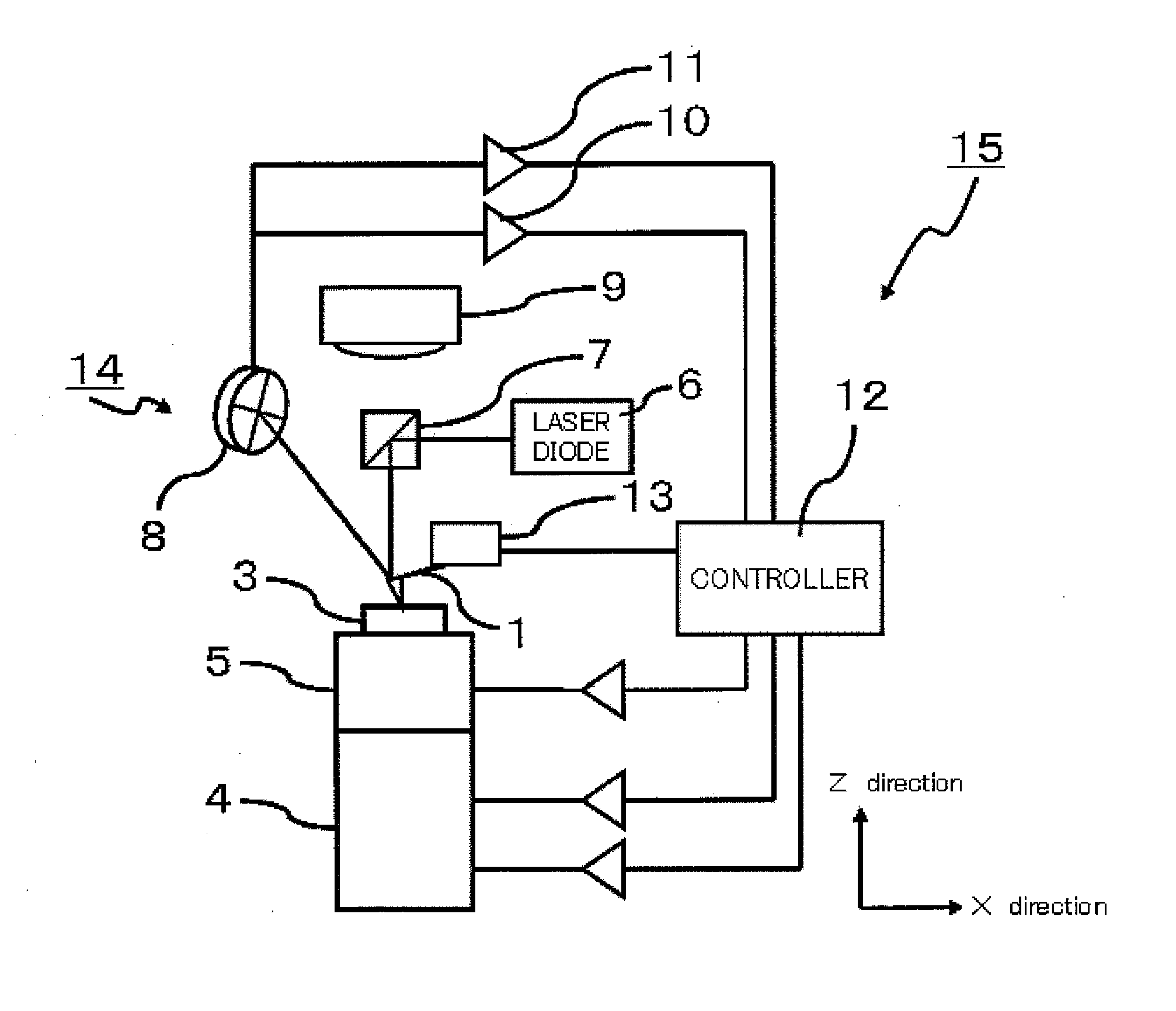
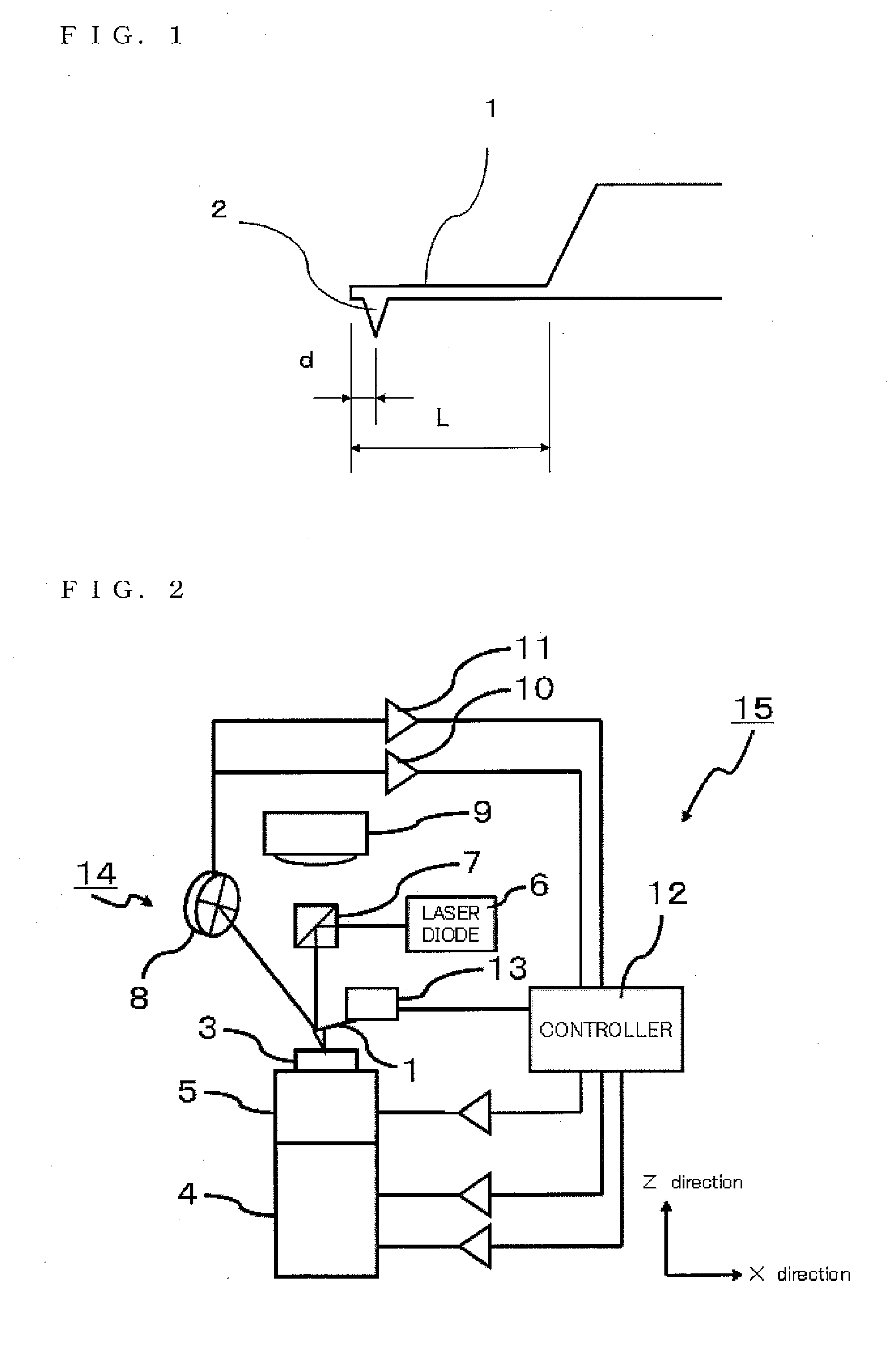
[0021]FIG. 2 illustrates a main structure of an example of a friction force microscope according to the present invention.

[0022]The friction force microscope according to the present invention includes an X-Y drive mechanism 4 for scanning a relative position between a cantilever 1 and a sample 3 in an X-Y plane parallel to a sample surface, a Z drive mechanism 5 for displacing the relative position in a Z direction perpendicular to the X-Y plane, and displacement information detection means 14 for detecting individual pieces of displacement information that are amplitudes of deformations in a bending direction and in a torsional direction generated in the cantilever 1 by an interatomic force between the tip of the probe 2 and the sample 3, when the relative position between the cantilever 1 and the sample 3 is displaced in a state in which (or when) a probe 2 fixed to a vicinity of th...


PUM


Abstract

Provided is a friction force microscope that can measure a friction force by a cantilever in a quantitative manner. The friction force microscope includes a friction force calculating mechanism that calculates an effective probe height and a torsional spring constant of the cantilever from bending sensitivity determined from displacement information in a bending direction of the cantilever and torsional sensitivity determined from displacement information in a torsional direction of the cantilever, respectively, so as to use the calculated values for calculating the friction force.

Description

BACKGROUND OF THE INVENTION[0001]1. Field of the Invention[0002]The present invention relates to a friction force microscope for measuring a friction force based on degree of a torsion of a cantilever in a scanning probe microscope.[0003]2. Description of the Art[0004]A friction force microscope is developed as an apparatus for measuring a friction force between a sample and a probe tip of a cantilever in a scanning probe microscope, and a basic principle thereof is as follows. Under a state in which the probe tip of the cantilever is brought into contact with the sample, the sample is scanned in a direction perpendicular to a longitudinal direction of the cantilever. Then, a displacement amount, at that time, in a torsional direction of the cantilever is obtained in each position, to thereby generate an image of a distribution of the friction force in a measurement range (see Japanese Patent Application Laid-open No. Hei 6-241762).[0005]However, a conventional friction force micros...

Claims


Application Information

Patent Timeline
Patent Type & Authority Applications(United States)
IPC IPC(8): G01Q70/08
CPCB82Y35/00G01Q60/24G01Q60/22G01Q60/26
Inventor YASUTAKE, MASATOSHIWATANABE, MASAFUMI
Owner HITACHI HIGH TECH SCI CORP
Why Eureka
Try Eureka