Coriolis mass flowmeter

a mass flowmeter and coriolis technology, applied in the direction of direct mass flowmeters, volume/mass flow by electromagnetic flowmeters, coils, etc., can solve the problems of increasing production costs, increasing and breaking of conductors, so as to reduce the risk of flashover

Inactive Publication Date: 2012-09-13
KRONE GMBH
View PDF9 Cites 11 Cited by
  • Summary
  • Abstract
  • Description
  • Claims
  • Application Information

AI Technical Summary

Benefits of technology

[0007]Based on the above-mentioned prior art, a primary object of the present invention is to provide a Coriolis mass flowmeter and a method for operating a Coriolis mass flowmeter with which common or even great forces for oscillation excitation can be provided, and at the same time, with which the risk of flashover is reduced.

Problems solved by technology

In a cable break in or on the coil caused by constant vibration, it is possible for a break to occur in the conductor, wherein this leads to a flashover due to the constant flow of current in the energy storage.
In addition to reducing the intensity of the current, which, however, goes hand in hand with a reduction of the intensity of the magnetic field and thus the power for oscillation excitation, such a measure can exist, for example, in casting of the coil, which is complex and increases the costs for production.
In particular, in Coriolis mass flowmeters having measuring tubes with a large nominal width or in using Corolis mass flowmeters with media having strongly damping characteristics, large coils with many windings are used, which have high energy during operation, thus increasing the risk of a flashover.

Method used


Image

  • Coriolis mass flowmeter
  • Coriolis mass flowmeter
  • Coriolis mass flowmeter

Examples


Embodiment Construction

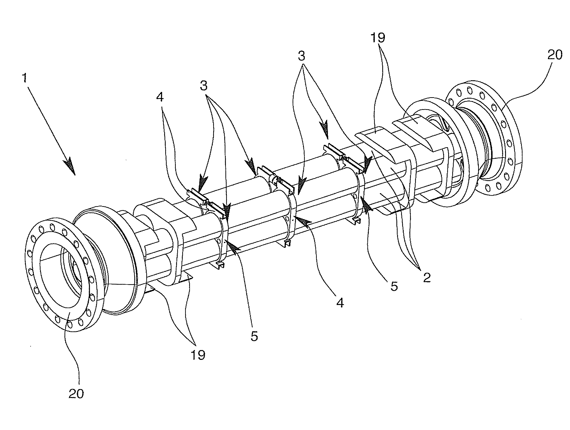
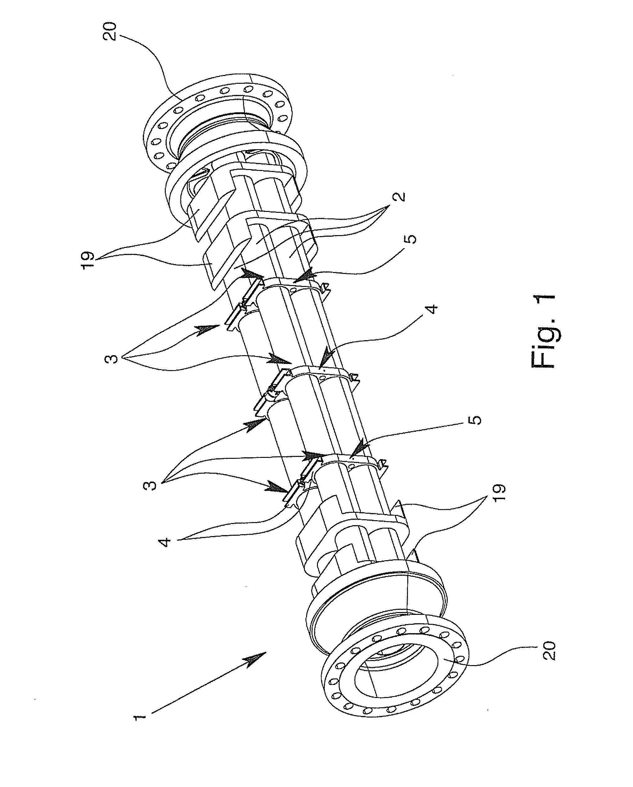
[0036]FIG. 1 shows a Coriolis mass flowmeter 1 with four straight measuring tubes running parallel 2. In this Coriolis mass flowmeter 1, two measuring tubes 2 are each combined into oscillation units using holding devices 3, which are excited to acceleration offset from one another during operation. The oscillation excitation of the two oscillation units occurs using an actuator assembly 4 that comprises two holding devices 3 that are arranged in opposition to each other, which hold the further components of the actuator assembly 4. The detection of the oscillation of the measuring tubes 2, or respectively, the oscillation units, is achieved using two sensor assemblies 5 that are arranged upstream and downstream from the actuator assembly 4 and which also comprises two holding devices 3 that are arranged in opposition to each other and which hold the further components of the sensor assembly 5.

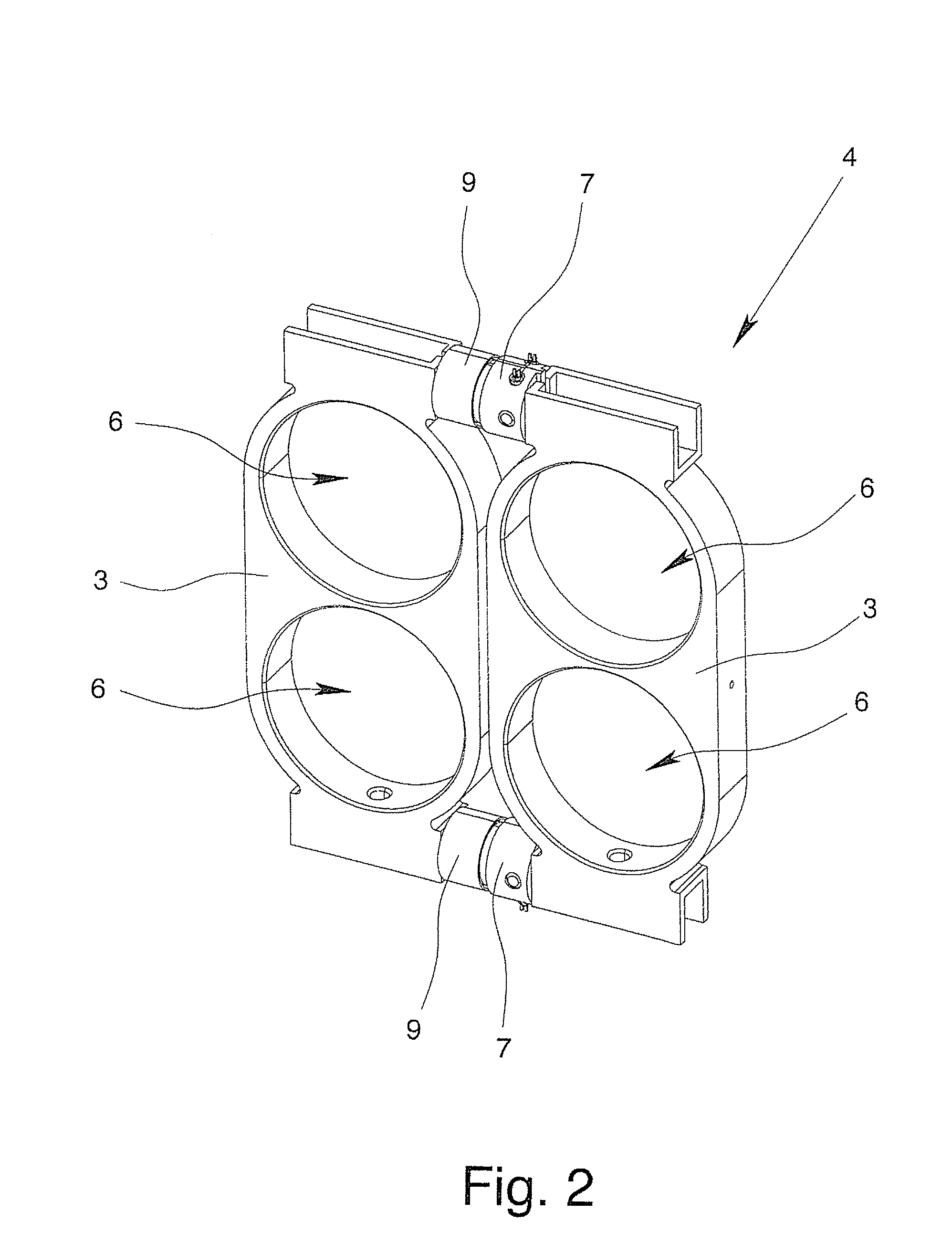
[0037]FIG. 2 shows an embodiment of an actuator assembly 4 having two holding devices 3. T...


PUM


Abstract

A Coriolis mass flowmeter in which common or even great forces for oscillation excitation can be guaranteed, and at the same time, with which the risk of flashover is reduced in explosion-proof surroundings is implemented in that the actuator assembly (4) has at least a first conductor (11) with windings (12) and at least a second conductor (13) with windings (14), the windings of the conductors being arranged parallel to one another. Also, the first conductor (11) and the second conductor (13) are insulated from one another at least in the area of their windings (12, 14) and the first conductor (11) and the second conductor (13) are connected in such a manner that the first conductor (11) and the second conductor (13) can be supplied with a current in the same manner in the operating state so that a common magnetic field is created.

Description

BACKGROUND OF THE INVENTION[0001]1. Field of the Invention[0002]The invention relates to a Coriolis mass flowmeter having at least one measuring tube and at least one actuator assembly, wherein the actuator assembly includes at least one first conductor with windings and at least one adjusting element. Furthermore, the invention relates to a method for operating a Coriolis mass flowmeter with at least one actuator assembly, wherein the actuator assembly includes at least windings of a first conductor and windings of a second conductor running parallel thereto and wherein the first conductor and the second conductor are isolated from one another at least in the area of the windings.[0003]2. Description of Related Art[0004]Mass flowmeters using the Coriolis principle have been known for many years and allow for determination of the mass flow rate of the medium flowing through the measuring tube with high accuracy. In order to determine the mass flow rate, the measuring tube having an ...

Claims


Application Information

Patent Timeline
Patent Type & Authority Applications(United States)
IPC IPC(8): G01F1/84
CPCG01F1/8422H01F5/00G01F1/8495G01F1/58G01F1/849
Inventor JUKES, EDWARD
Owner KRONE GMBH
Why Eureka
Try Eureka