
Impact locating day and night marker for a projectile

Active Publication Date: 2012-09-13
RHEINMETALL WAFFE MUNITION GMBH
View PDF9 Cites 18 Cited by
  • Summary
  • Abstract
  • Description
  • Claims
  • Application Information

AI Technical Summary

Benefits of technology

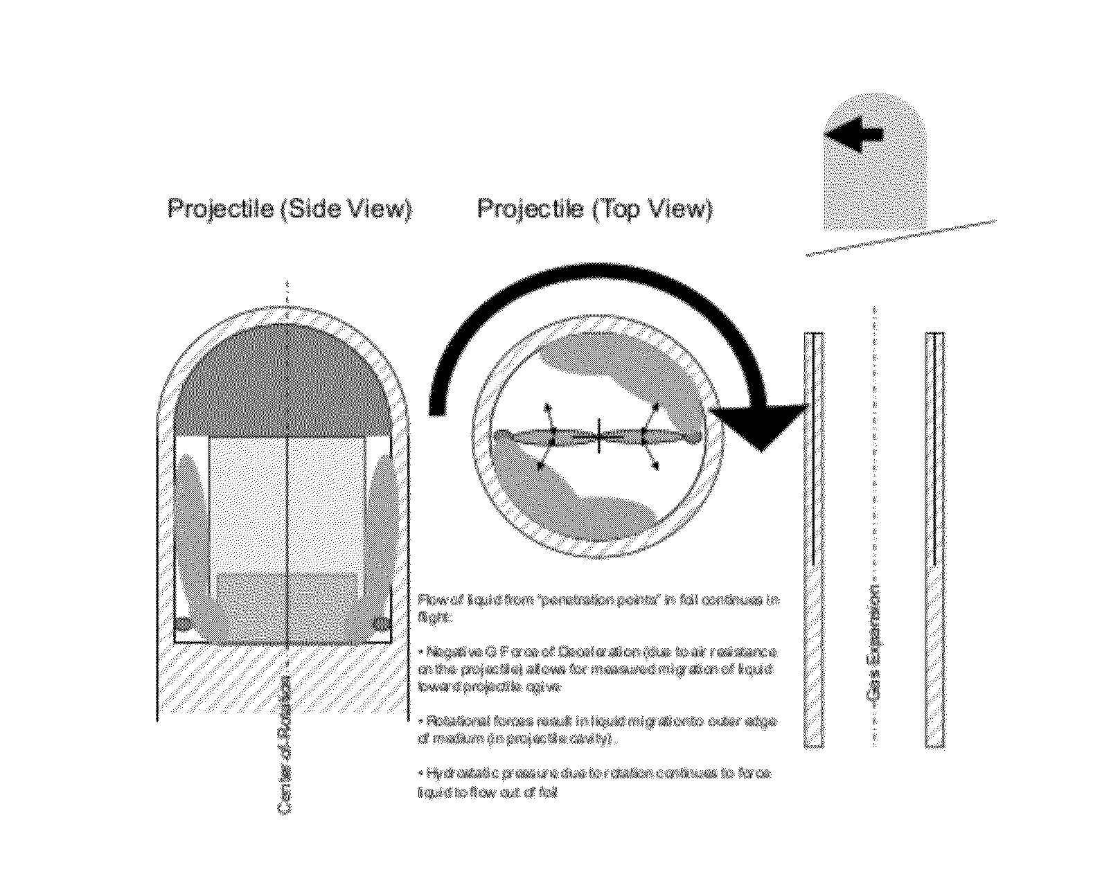
[0009]These objects, as well as further objects which will become apparent from the discussion that follows are achieved, in accordance with the present invention, by designing the frangible compartments in such a way that, instead of (or in addition to) utilizing the forces at acceleration set-back to mix the liquid chemical components, they utilize centrifugal forces to initiate mixing. Upon launch of the projectile, the projectile rotation that is induced by lands and grooves in the barrel of the weapon imparts a centrifugal force on one or more masses that are suspended in the chemical components disposed within their respective compartments. The resulting outward motion of the masses causes them to penetrate the foil packaging material of the compartments, releasing the liquid into a surrounding medium, which may, for example, be a dry powder. This medium provides for even distribution of the reacting liquid while the projectile is in flight.

Problems solved by technology

While this arrangement is satisfactory under most conditions, it is not fully reliable in that the frangible partition can sometimes withstand the acceleration and centrifugal forces experienced during launch, so that it does not break and allow mixing of the components.

Method used


Image

  • Impact locating day and night marker for a projectile
  • Impact locating day and night marker for a projectile
  • Impact locating day and night marker for a projectile

Examples


Embodiment Construction

[0040]The preferred embodiments of the present invention will now be described with reference to FIGS. 1-7 of the drawings. Identical elements appearing the various figures are designated with the same reference numerals.

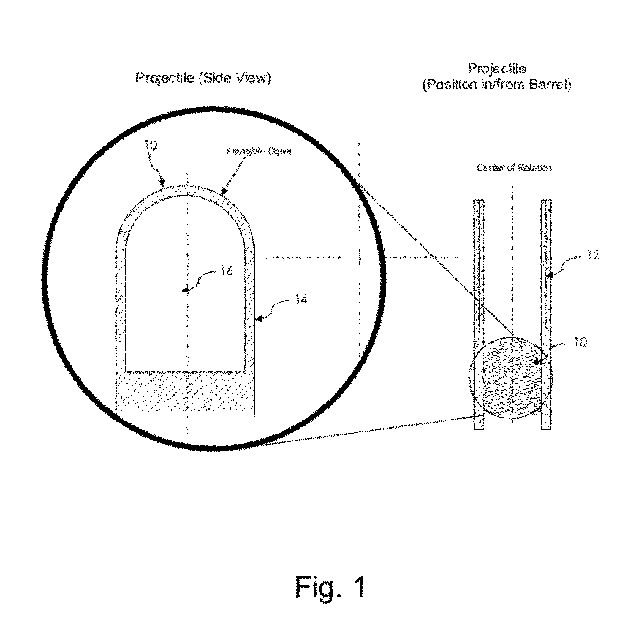
[0041]FIG. 1 shows a projectile 10 disposed in the chamber of a weapon with a barrel 12, prior to firing and setback. As illustrated in the exploded and cross-sectional view, the projectile 10 comprises a hollow projectile body 14 having a void 16 at the projectile head.

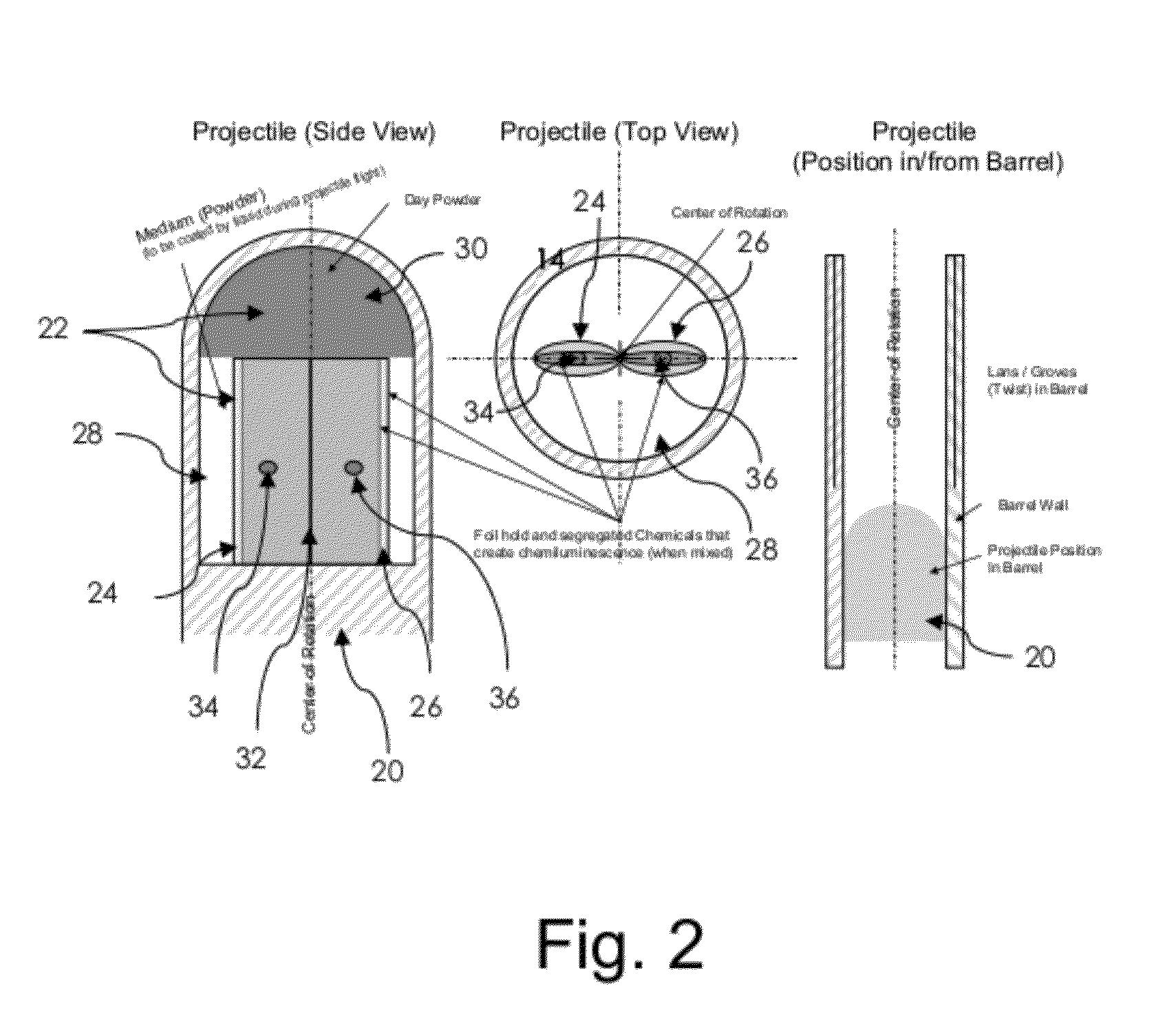
[0042]FIG. 2 shows a projectile 20 having a marking device 22 in accordance with the preferred embodiment of the present invention, disposed in the projectile head. This marking device comprises four elements:

[0043]1. A pair of adjacent compartments 24 and 26 formed of frangible foil, each containing a separate liquid component such that, when the two components are mixed together, they chemically react. These components are preferably either chemi-luminescent or exothermic, or both.

[0044]The two com...


PUM


Abstract

A marking projectile comprises separate compartments that break during launch due to rotation of the projectile as it leaves the barrel of a weapon. Metal pellets contained within the compartments are pressed outward and pierce the compartment walls. This allows for mixing of chemical materials contained within the compartments, so that the materials substantially react by the time the projectile strikes a target. The chemical materials may be a pair of chemi-luminescent components, or components that create heat for thermal marking.

Description

CROSS-REFERENCE TO RELATED APPLICATION[0001]This application claims priority from Provisional Patent Application No. 61 / 271,452, filed Jul. 21, 2009.BACKGROUND OF THE INVENTION[0002]The present invention relates to the field of practice ammunition and, specifically, to an ammunition projectile that can mark its point of impact both by day and by night.[0003]More particularly, the invention concerns a device, incorporated into a projectile, that provides for marking the point of impact of the projectile when the projectile strikes a target. As used herein, the term “projectile” is intended to include both mortar ammunition and artillery ammunition.[0004]Impact marking projectiles are well known in the art. Marking projectiles which use a dry powder, such as a red powder dye, for marking the impact by day are known, for example, from the U.S. Patent Publication No. 2006 / 0032393 to Haeselich. Marking projectiles which use chemi-luminescent materials for marking their impact by night ar...

Claims


Application Information

Patent Timeline
IPC IPC(8): F42B12/40
CPCF42B12/40F42B12/46F42B12/382F42B8/14
Inventor SULLIVAN, KEVIN MICHAEL
Owner RHEINMETALL WAFFE MUNITION GMBH
Learn More