
Rear suspension system for bicycles

a rear suspension and bicycle technology, applied in the field of rear suspension systems, can solve the problems of low efficiency of reducing shock and easy discomfort of cyclists, and achieve the effect of stable status of bicycles

Inactive Publication Date: 2012-09-13
KINESIS INDUSTRY
View PDF1 Cites 36 Cited by
  • Summary
  • Abstract
  • Description
  • Claims
  • Application Information

AI Technical Summary

Benefits of technology

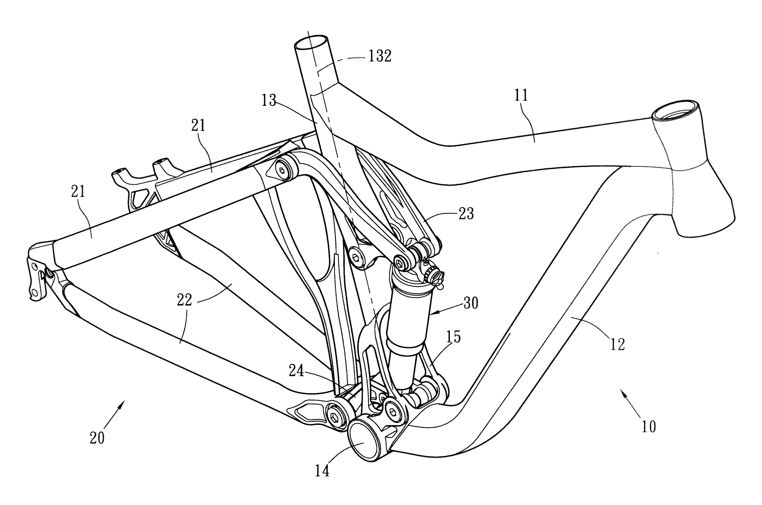
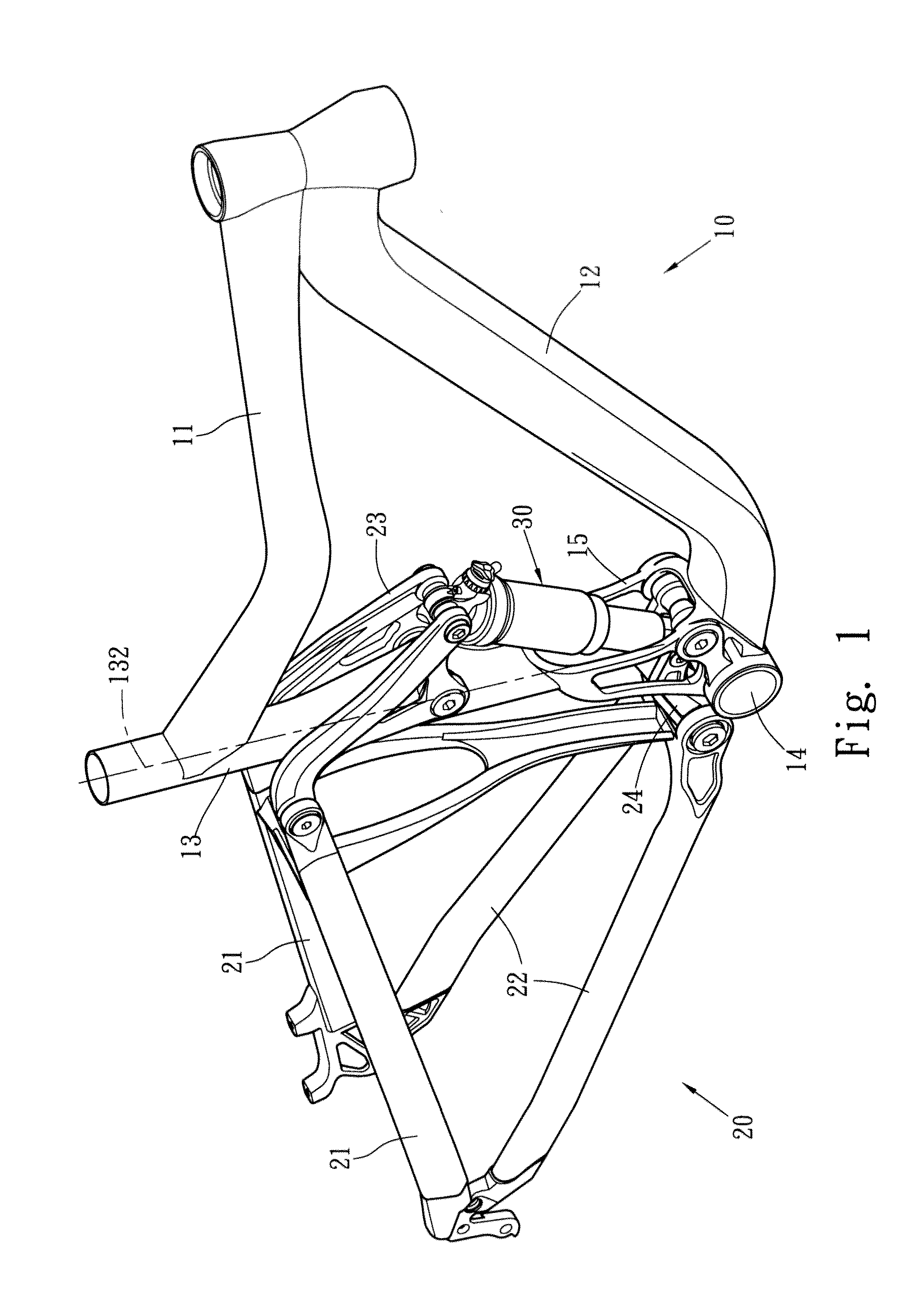
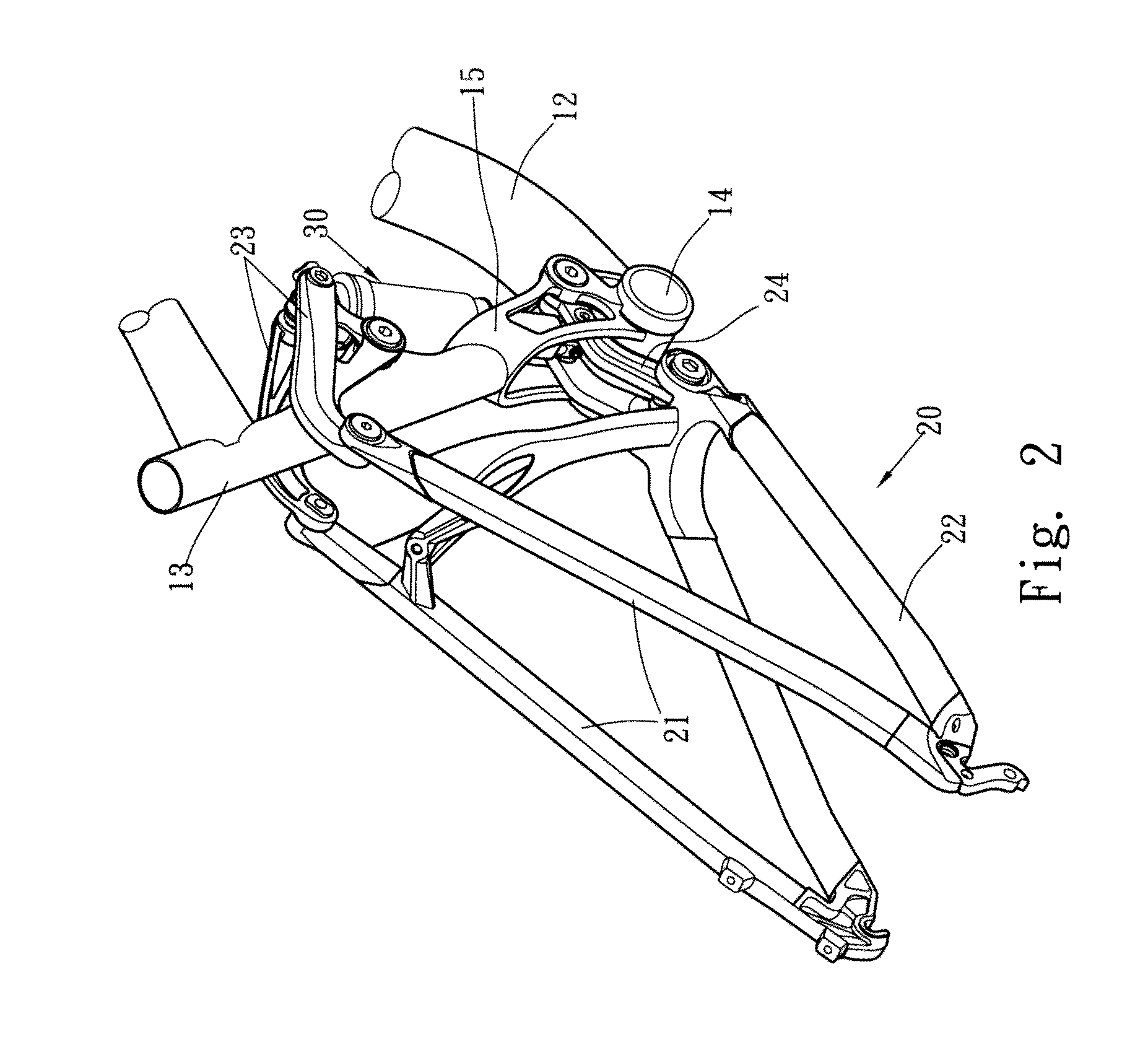
[0013]The present invention relates to a rear suspension system for bicycles and comprises a front part and a rear part, wherein the front part has a top tube, a down tube and a seat bracket, and the rear part has seat stays and chain stays. A lower end of the down tube is connected to the bottom bracket and a lower end of the seat tube has a substantially inverted U-shaped frame connected thereto which is located close to the bottom bracket. The frame extends upward from the bottom bracket and defines a space with the bottom bracket. The chain stays have first ends connected to first ends of the seat stays. A top link unit is connected to second ends of the seat stays. The top link unit is pivotably connected to a mediate portion of the seat tube and extends toward the front part to form a first pivotal portion. Two respective second ends of the chain stays are connected to a first end of a down link unit and a second end of the down link unit extends into the frame. A second pivotal portion is formed at the mediate portion of the down link unit. A shock-absorbing device has a top end pivotably connected to the first pivotal portion and a lower end of the shock-absorbing device extends into the frame and is pivotably connected to the second pivotal portion. The lower end of the down link unit and the lower end of the shock-absorbing device are both located close to the axis of the seat tube can maintain the stability of the bicycle when the shock-absorbing device is in operation.

Problems solved by technology

Besides, the shock-absorbing device is located at a distance from the axis of the seat tube, and this cannot accept the impact to the seat tube, so that the efficiency for reducing the shock is low.
The seat tube is a cylindrical and circular tube which directly transfers the impact to the cyclist's hip so that the cyclist easily feels discomfort.

Method used


Image

  • Rear suspension system for bicycles
  • Rear suspension system for bicycles
  • Rear suspension system for bicycles

Examples


Embodiment Construction

[0021]Referring to FIGS. 1 to 4, the rear suspension system for bicycles of the present invention comprises a front part 10, a rear part 20 and a shock-absorbing device 30 connected between the front part 10 and the rear part 20.

[0022]The front part 10 has a top tube 11, a down tube 12 and a seat bracket 13. The lower end of the down tube 12 is connected to the bottom bracket 14 and the lower end of the seat tube 13 has a substantially inverted U-shaped frame 15 connected thereto which is located close to the bottom bracket 14. The frame 15 extends upward from the bottom bracket 14 and defines a space with the bottom bracket 14. The mediate portion of the seat tube 13 has a protrusion 131 extending toward a direction opposite to the front part 10. Two sides of the substantially inverted U-shaped frame 15 each have an opening 151 communicating with the space in the frame 15.

[0023]The rear part 20 has seat stays 21 and chain stays 22. The chain stays 22 have two respective first ends ...


PUM


Abstract

A rear suspension system for a bicycle which includes a front part having a top tube, a down tube and a seat bracket, and a rear part has seat stays and chain stays. The seat tube has a frame located close to the bottom bracket. A top link unit is pivotably connected to the seat stays and extends toward the front part to form a first pivotal portion. The chain stays are connected to a down link unit which extends into the frame. A second pivotal portion is formed at the mediate portion of the down link unit. A shock-absorbing device has its top end pivotably connected to the first pivotal portion and the lower end of the shock-absorbing device extends into the frame and is pivotably connected to the second pivotal portion which is located close to the axis of the seat tube to provide stable buffering action.

Description

FIELD OF THE INVENTION[0001]The present invention relates to a rear suspension system, and more particularly, to a rear suspension system for bicycles and which reduces impact to the seat tube.BACKGROUND OF THE INVENTION[0002]A conventional rear suspension system is mainly used on mountain bikes and the rear suspension system buffers the impact to the bicycle frame from the ground so as to increase comfort to the cyclists. The conventional rear suspension system generally includes the seat stays, the chain stays and the shock-absorbing device.[0003]The design to the rear suspension system has to consider multiple factors including the position, the angle, the efficiency of the shock-absorbing feature, the buffering actions, the stiffness of the bicycle frame and the connection parts. Therefore, there are many different types of rear suspension systems.[0004]A conventional rear suspension system is disclosed in Taiwan Utility Patent No. 087219571 and the bicycle frame includes a fron...

Claims


Application Information

Patent Timeline
IPC IPC(8): B62K19/36B62K19/30
CPCB62K25/286B62K25/28
Inventor TSENG, JIMMY
Owner KINESIS INDUSTRY
Learn More