Unlock instant, AI-driven research and patent intelligence for your innovation.
Panoramic Image Preparing Method And Three-Dimensional Laser Scanner
Active Publication Date: 2012-09-13
KK TOPCON
View PDF5 Cites 20 Cited by
Summary
Abstract
Description
Claims
Application Information
AI Technical Summary
This helps you quickly interpret patents by identifying the three key elements:
Problems solved by technology
Method used
Benefits of technology
Benefits of technology
[0008]It is an object of the present invention to provide a panoramic image preparing method for optimizing contrast in a panoramic image corresponding to a measurement range and a three-dimensional laser scanner for acquiring image data so that the contrast in the panoramic image becomes optimal.
[0019]According to the present invention, the panoramic image preparing method comprises a step of setting a measurement range so as to include objects to be measured, a step of dividing the measurement range as required and setting two or more sections and a step of synthesizing partial images photographed for each of the sections and preparing a panoramic image, a step of photographing each of the sections under two or more image pickup conditions and a step of synthesizing the panoramic image by using the partial image photographed under an optimal image pickup condition at least about the object to be measured. As a result, a high quality image can be acquired about the object to be measured at any position of the panoramic image.
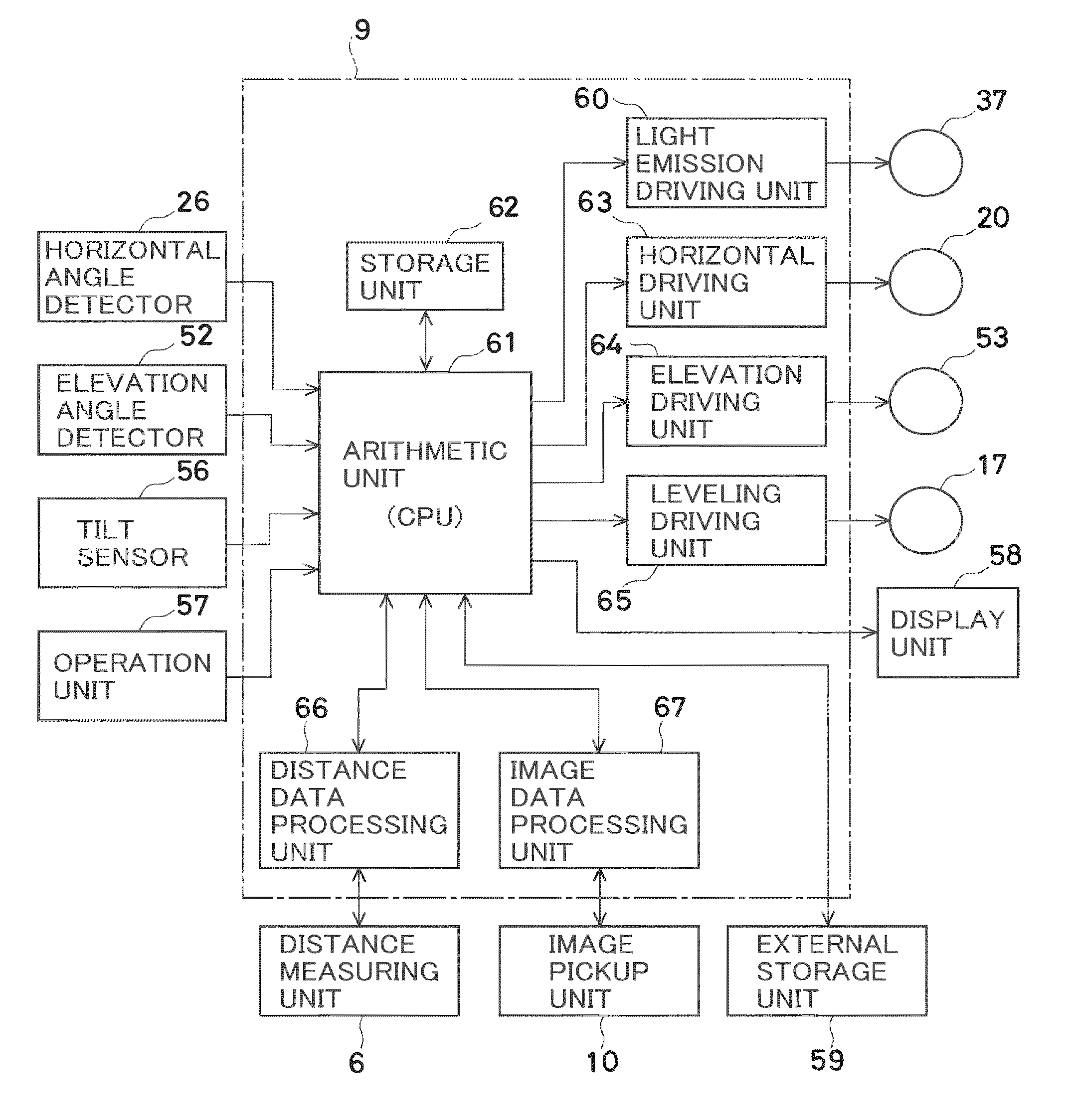
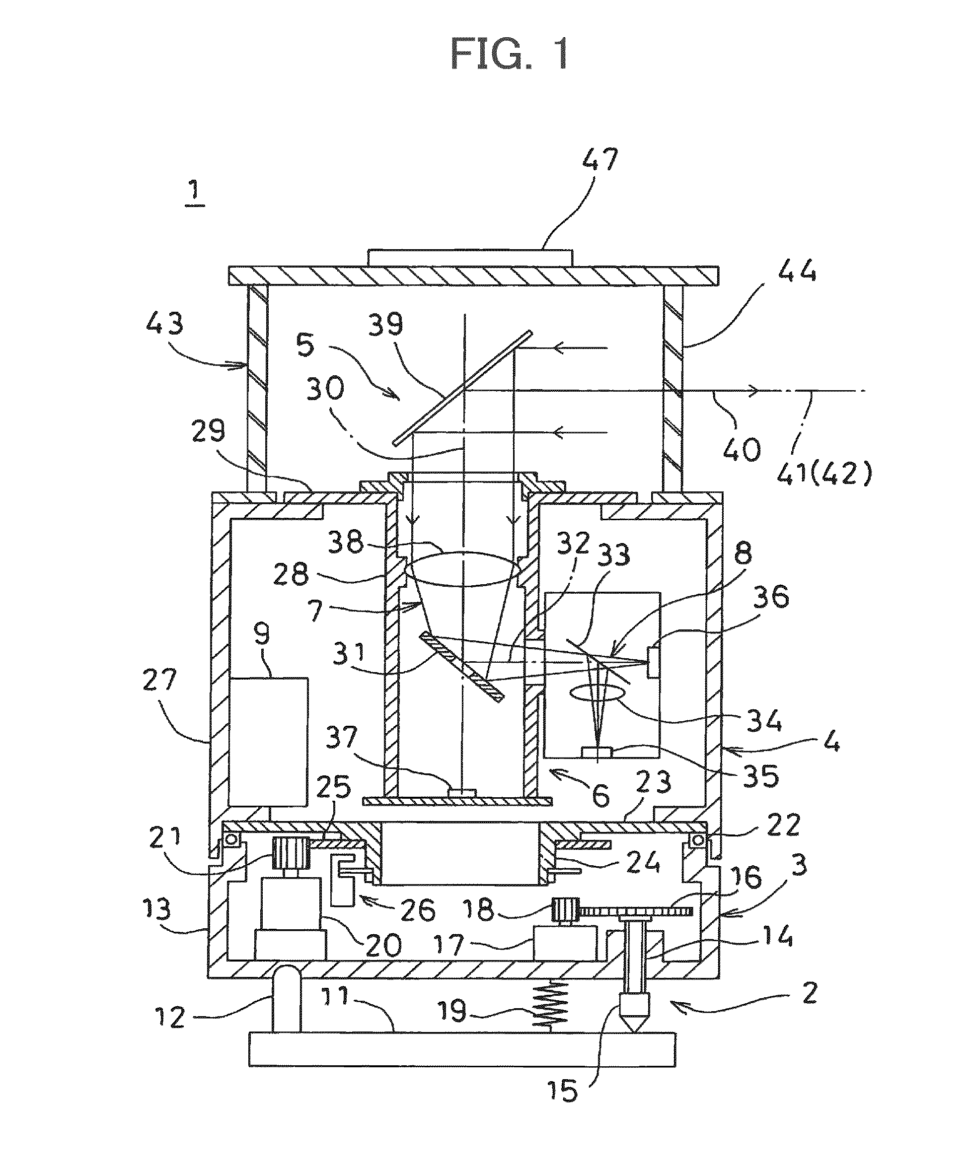
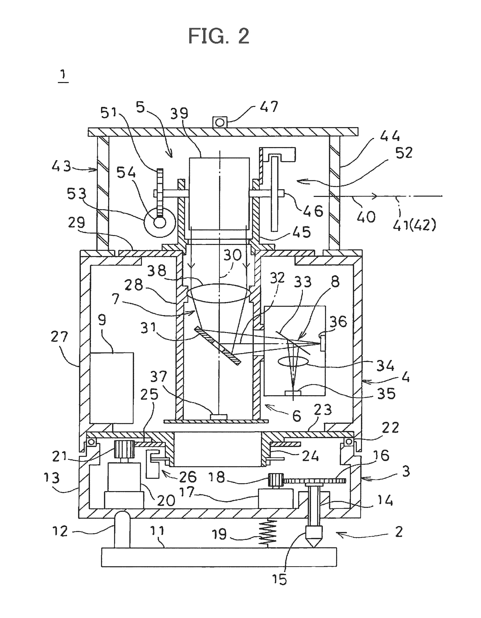
[0020]Furthermore, according to the present invention, the three-dimensional laser scanner comprises a light source for emitting a distance measuring light as pulsed light, a projection optical system for projecting the distance measuring light from the light source to a measurement range, a photodetection unit for receiving a reflected distance measuring light, a scanning unit for scanning the measurement range with the distance measuring light, an angle detection unit for detecting a projecting direction of the distance measuring light, a distance measuring unit for calculating a distance to an object to be measured located in the measurement range based on photodetection signals from the photodetection unit, an image pickup unit for acquiring an image of the measurement range, and a control unit for controlling the light source, the photodetection unit, the scanning unit, the distance measuring unit, and the image pickup unit, and in the three-dimensional laser scanner, the control unit calculates three-dimensional data based on an angle detection signal from the angle detection unit and based on a distance measurement result from the distance measuring unit, sets the measurement range so as to include the object to be measured, divides the measurement range into at least two or more sections, photographs each section and acquires a partial image, synthesizes the partial images and prepares a panoramic image of the measurement range, and at least about the partial image of the section including the object to be measured out of the partial images to be synthesized is photographed under the optimal image pickup condition. As a result, a high quality image can be acquired about the object to be measured at any position in the panoramic image.
Problems solved by technology
However, brightness is usually different depending on a direction of photographing and a photographing position, and if the contrast is adjusted at the center photographing range 84, the contrast no longer becomes optimal in a part, which is too bright, and in a part which is too dark as exemplified in FIG. 9.
Therefore, the color information of image data acquired by photographing with the contrast, which is not optimal, is attached with respect to the measuring point of the part, which is too bright or too dark.
Method used
Image
Click on the blue label to locate the original text in one second.
Reading with bidirectional positioning of images and text.
Examples
second embodiment
[0092]FIG. 6 illustrates a second embodiment in which the contrasts of the objects to be measured 72, 73, and 74 are optimal.
[0093]In FIG. 6A, FIG. 6B, and FIG. 6C, partial images are acquired with different contrasts, respectively, and FIG. 6D illustrates a panoramic image synthesized for each contrast.
[0094]FIG. 6A illustrates a panoramic image 80a (normal image) which is photographed by setting the contrast using a center of the image as a reference and is synthesized, and the object to be measured 73 located at the center has an optimal reference contrast.
[0095]FIG. 6B illustrates a panoramic image 80b acquired by synthesizing partial images which are photographed by making exposure time longer so as to increase brightness. Under this image pickup condition, the object to be measured 72 photographed with lower brightness has the optimal contrast, but the object to be measured 73 and the object to be measured 74 have overexposure, that is, the image is too bright and sufficient c...
third embodiment
[0101]FIG. 7 illustrates a third embodiment in which the contrast is set so that the whole panoramic image has the optimal contrast in a case where the panoramic image is to be acquired.
[0102]In the photographing to acquire the panoramic image, a direction of the image pickup device is sequentially changed, and there are a direction where an object is photographed bright and a direction where an object is photographed dark. For example, under the strong sunlight, in a direction facing the sun, which is a direction of backlight, the object is photographed dark, while in a direction with the back against the sun, the object is photographed bright or the like.
[0103]In this case, since it is known in advance that the brightness is different depending on a photographing direction, a measurement range 70 is set, and when the measurement range 70 is divided into sections 71, the contrast (brightness) is set for each section 71. For example, in a case where the brightness gets stronger from...
PUM
Abstract
A panoramic image preparing method comprises a step of setting a measurement range 70 so as to include objects to be measured 72, 73, and 74, a step of dividing the measurement range as required and setting two or more sections 71 and a step of synthesizing partial images 81 photographed for each of the sections and preparing a panoramic image 80, a step of photographing each of the sections under two or more image pickup conditions and a step of synthesizing the panoramic image by using the partial image photographed under an optimal image pickup condition at least about the object to be measured.
Description
BACKGROUND OF THE INVENTION[0001]The present invention relates to a panoramic image preparing method and a three-dimensional laserscanner.[0002]A three-dimensional laserscanner has been known as a surveying device for acquiring three-dimensional data (3D data) of an object to be measured in a short time.[0003]The three-dimensional laserscanner is installed at a reference point, scans a measurement range or an object to be measured with a pulse laser beam, measures a distance for each pulse laser beam and acquires point-group data. In a case where the point-group data is to be acquired in a wide range, the three-dimensional laser scanner is installed at other reference points, the three-dimensional laser scanner acquires the point-group data for an adjacent measurement range and synthesizes the acquired point-group data so as to make the acquirement of the point-group data in a wide range possible.[0004]Further, there is a three-dimensional laser scanner which comprises an image p...
Claims
Application Information
Patent Timeline
Application Date:The date an application was filed.
Publication Date:The date a patent or application was officially published.
First Publication Date:The earliest publication date of a patent with the same application number.
Issue Date:Publication date of the patent grant document.
PCT Entry Date:The Entry date of PCT National Phase.
Estimated Expiry Date:The statutory expiry date of a patent right according to the Patent Law, and it is the longest term of protection that the patent right can achieve without the termination of the patent right due to other reasons(Term extension factor has been taken into account ).
Invalid Date:Actual expiry date is based on effective date or publication date of legal transaction data of invalid patent.
