
Electrical Receptacle Enclosure

Inactive Publication Date: 2012-09-13
BOUSE ROY +1
View PDF11 Cites 10 Cited by
  • Summary
  • Abstract
  • Description
  • Claims
  • Application Information

AI Technical Summary

Benefits of technology

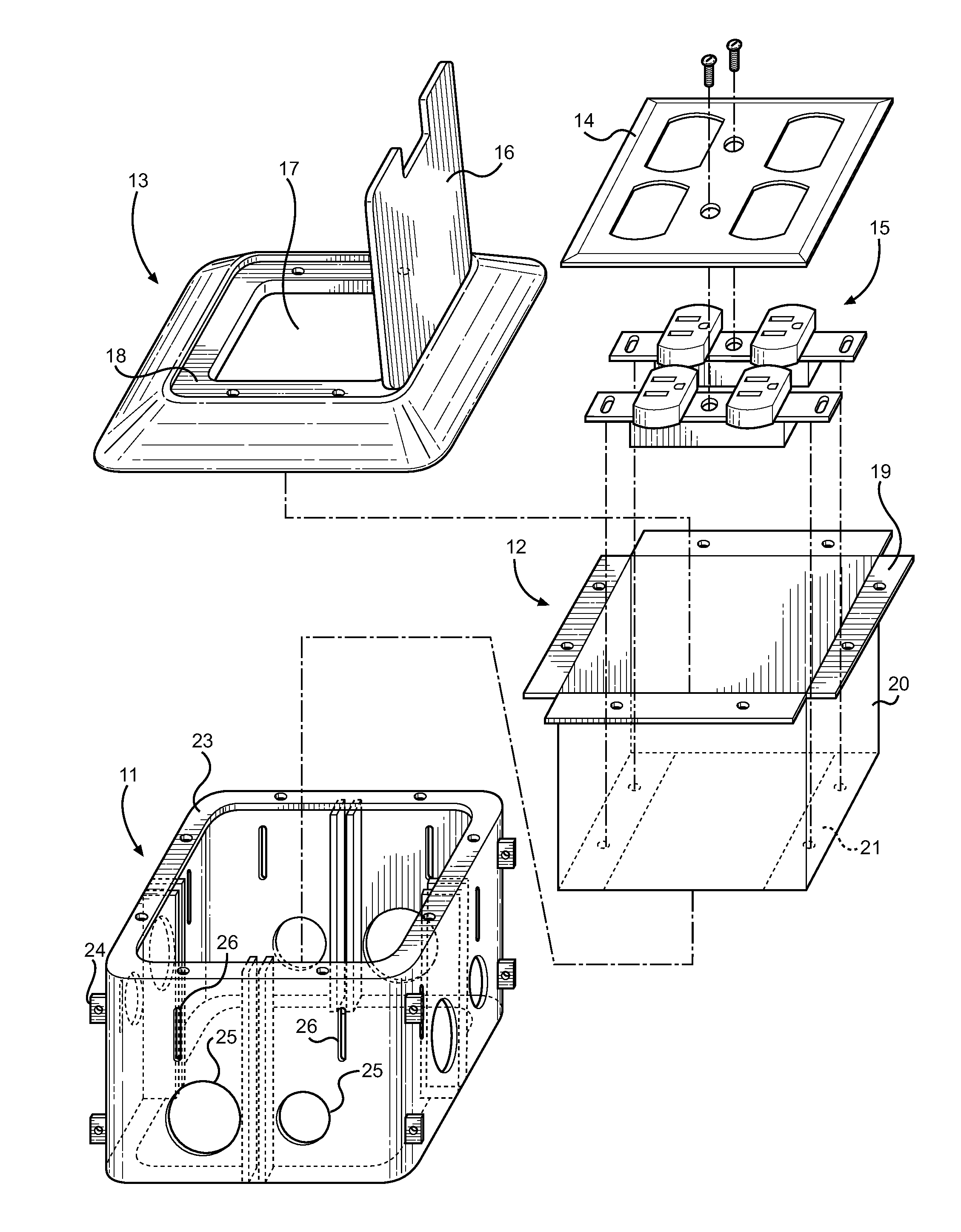
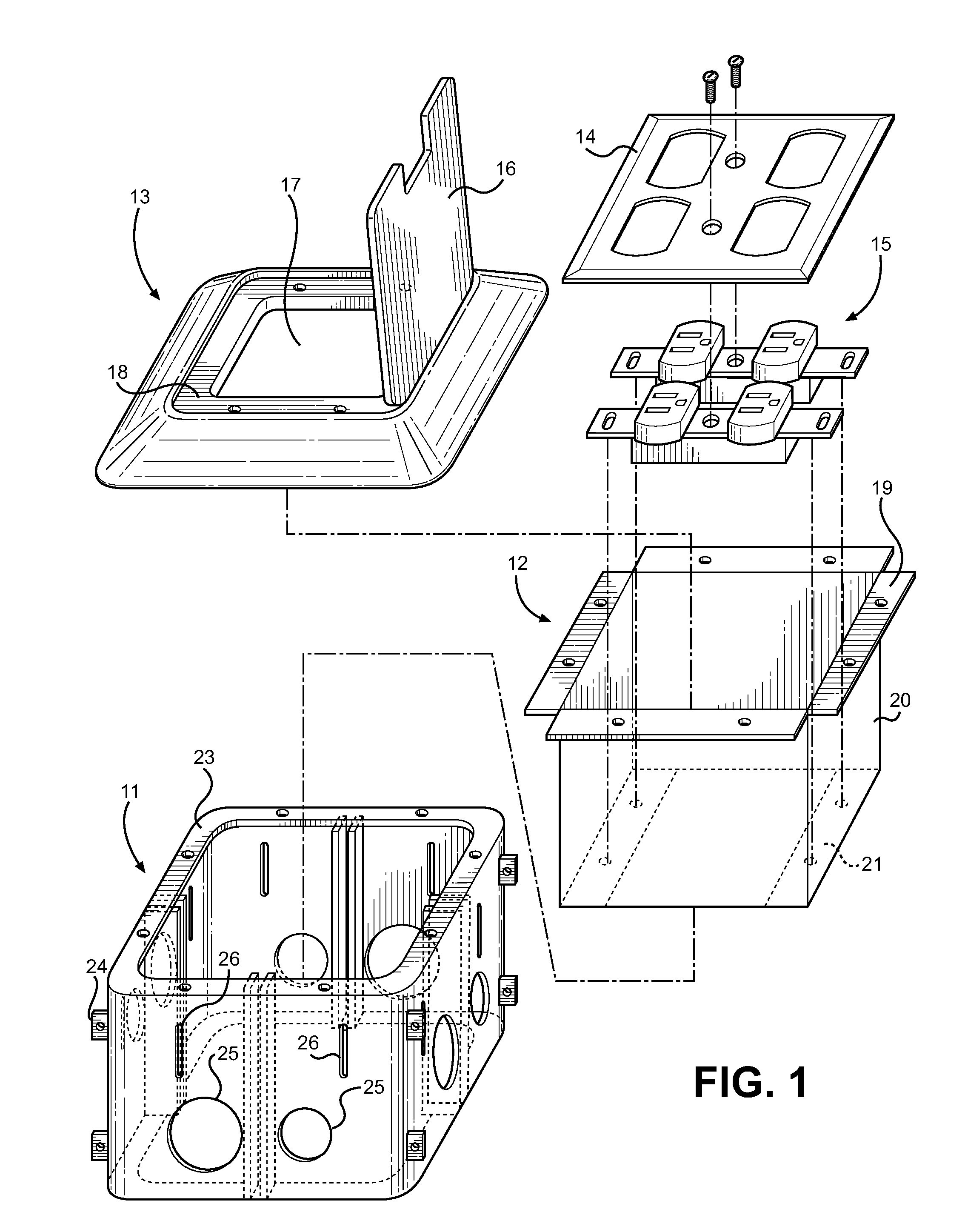
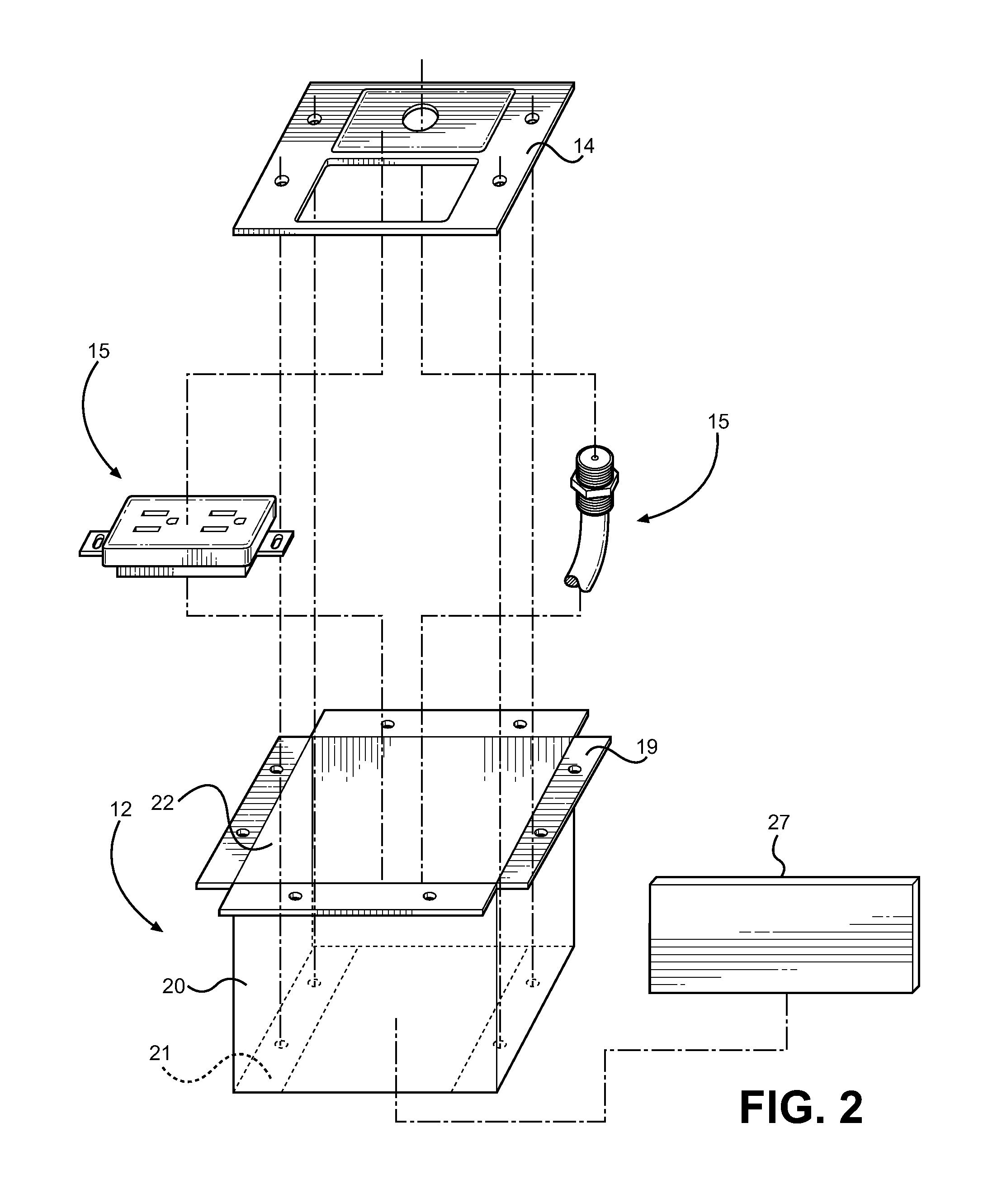
[0007]The present electrical box is installable into a number of different surfaces within a home, including within concrete or household flooring, along an upstanding wall, or further mounted from the ceiling. The primary advantage of the present invention is not only its outward flush-mount appearance and inset space for loose cords, but more specifically the installation methods associated with the elements of the box. The construction of the assembly allows the box to be structurally secured using a lower box, which includes structural mounting points and conduit knockouts to secure the box into place and to run necessary wiring to the desired fixtures. The middle box secures the fixtures, which are then connected to the wiring within the lower box and lowered thereinto. Finally, the upper lid covering is placed over the assembly, wherein the middle box is inserted into the lower box, whereafter fasteners are driven through all three components to secure all elements together. In this way, the installation is separated into the three primary steps using specific elements for each step: structural securement, fixture wiring and then lid installation.
[0009]Patents have been granted to several devices that attempt to improve the ease of installation of electrical floor boxes, and further to those emphasizing concealment and safety of electrical receptacles. However, the prior art fails to provide a device having a construction and assembly of components similar to the present invention, which improves the steps of installation and separates them into specific elements for each step.
[0010]Specifically, U.S. Pat. No. 4,536,612 to Domigan discloses an electrical floor box for raised floors, comprising a hollow main housing and a means of separating the housing into two power sections. The housing mounts wire connectors for each power section, while a passageway allows power connector to connect receptacles to the power sections. The separated power sections allow high and low voltage receptacles to be placed within the same box. While providing a unique receptacle box capable of separating power sources, the Domigan device is limited to raised floors wherein access behind the main housing is required for securement thereof to the floor. The present invention is capable of mounting in a number of different flooring or wall types, including those where access behind the wall or floor is not possible. The lower box of the present invention is capable securing to wall studs, floor supports or be secured by external footings in concrete floors. The Domigan further is limited to being anchored into a wood flooring and not anchored into concrete, and further requires its internal electrical fixture to face inwards, limiting plug cord access over a vertical design. The present invention provides a separating divider between high and low voltage lines without sacrificing ergonomics of plugging in cords.
[0011]U.S. Pat. No. 7,989,711 to Jolly discloses a floor box that is particularly suited for ultra shallow floor installations. The installation comprises a body having a base and perimeter side wall, and a cover having a cover body and cover lid. The side wall is adapted to be raised above the floor level, while the cover is provided to close off the base and cover the raised portion of the perimeter sidewall. The fixtures of the Jolly device are adapted to rest in a vertical orientation along the upstanding perimeter sidewall of the installation, wherein single gang outlets are installed for electrical plug connection. While this provides a device for shallow floor environments, the Jolly device does not disclose the novel installation elements and flexibility with which the device may be installed or the flexibility with respect to the chosen fixtures therein.
[0012]U.S. Pat. No. 6,878,877 and U.S. Published Patent Application Publication 2005 / 0167141 to Cozzi disclose an electrical outlet box assembly having an outlet box, an electrical fixture assembly and an adapter. The adapter is located between the box and the electrical fixture, wherein the height of the adapter may be adjusted relative to the outlet box to adjust for different floor or wall covering material thicknesses. This adjustment of the adapter allows the outlet box to be positioned well below floor level, while the electrical fixture assembly may be raised to floor level and cover by a face plate for a flush outward appearance. While the adapter provides a means to support a fixture within a larger box that is secured within the floor, the purpose and design of the Cozzi device diverges in intent and design from the present invention, which discloses a middle box within a secure lower box and the middle box is adapted to secure electrical fixtures within the interior of the assembly and then be covered by a lid structure for access. It is not desired to position the fixture at floor level, but rather to disclose an accessible floor box having an open interior that allows access for a plurality of different electrical plugs for access to power or electrical signals.
[0013]The Cozzi devices is also limited in the fact that it cannot be installed into a cement floor, but rather only into a wood floor due to the flanges connecting the outlet box and the electrical fixture on the top of the assembly. An attached plug into the electrical fixture makes connection at floor level, which does not allow for the ability to hide a length of cord within the outlet box interior, creating a trip hazard and unsightly run of excess cord. Further, once the outlet box of Cozzi is installed, you cannot remove it from the floor because it is mounted onto the sub floor and not the finished floor. This is inconvenient when you need to install a box after the finished top flooring is in place, as the lid will flushly mount to the flooring surface as the outlet box cannot be mounted below the finished flooring, and the stages of the box will not sandwich the finished flooring between the insert and the outlet box. This elevates the assembly and the cover plate above the floor surface, which is not desirable.

Problems solved by technology

However, the prior art fails to provide a device having a construction and assembly of components similar to the present invention, which improves the steps of installation and separates them into specific elements for each step.
While providing a unique receptacle box capable of separating power sources, the Domigan device is limited to raised floors wherein access behind the main housing is required for securement thereof to the floor.
The Domigan further is limited to being anchored into a wood flooring and not anchored into concrete, and further requires its internal electrical fixture to face inwards, limiting plug cord access over a vertical design.
While this provides a device for shallow floor environments, the Jolly device does not disclose the novel installation elements and flexibility with which the device may be installed or the flexibility with respect to the chosen fixtures therein.
The Cozzi devices is also limited in the fact that it cannot be installed into a cement floor, but rather only into a wood floor due to the flanges connecting the outlet box and the electrical fixture on the top of the assembly.
An attached plug into the electrical fixture makes connection at floor level, which does not allow for the ability to hide a length of cord within the outlet box interior, creating a trip hazard and unsightly run of excess cord.
Further, once the outlet box of Cozzi is installed, you cannot remove it from the floor because it is mounted onto the sub floor and not the finished floor.
This is inconvenient when you need to install a box after the finished top flooring is in place, as the lid will flushly mount to the flooring surface as the outlet box cannot be mounted below the finished flooring, and the stages of the box will not sandwich the finished flooring between the insert and the outlet box.
This elevates the assembly and the cover plate above the floor surface, which is not desirable.
As such, applications of these utilitarian inventions will not be desirable in a home or office in which both aesthetics and functionality are a concern.
It is unlikely that home use will necessitate or even allow the installation of such commercial boxes.
The invention described in Markiewicz fails to address the issues of floor mounted electrical box installation, concealment and safety, and further does not address the ability to mount in different flooring or wall locations using the same assembly.
During use, the door on the surface of the receptacle box must remain open, resulting in an unsightly and potentially dangerous issue, thereby limiting the receptacle to temporary usage.

Method used


Image

  • Electrical Receptacle Enclosure
  • Electrical Receptacle Enclosure
  • Electrical Receptacle Enclosure

Examples


Embodiment Construction

[0032]Reference is made herein to the attached drawings. Like reference numerals are used throughout the drawings to depict like or similar elements of the electrical receptacle enclosure. For the purposes of presenting a brief and clear description of the present invention, the preferred embodiment will be discussed as used for providing an improved construction for ease of installation and greater flexibility with regard to installation. The figures are intended for representative purposes only and should not be considered to be limiting in any respect.

[0033]Referring now to FIG. 1, there is shown an exploded perspective view of the electrical receptacle enclosure of the present invention. The assembly comprises three main elements that form the structure of the enclosure and allow the assembly to be installed in several different surface types. The assembly is secured to one or more structural ground supports using a lower box 11, which comprises a hollow enclosure having an open...


PUM


Abstract

Disclosed is an improved electrical receptacle enclosure assembly adapted increase flexibility with respect to its installation procedures, its installed location and supported electrical fixtures therein. The assembly comprises a structurally supported lower box, a middle box adapted to fit within the interior of the lower box, and an upper cover adapted to flushly mount against a mounting surface over the lower and middle boxes. The lower box includes structural mounting points, conduit knockout plates and an open upper and lower portion. The middle box comprises a lower box insert having fixture mounting points and a securing shelf adapted to connect to the lower box upper portion. Electrical fixtures are secured within the middle box and are electrically connected therebelow and covered by a fixture faceplate within the middle box. An upper cover connects the assembly together and rests against a mounting surface for a clean, flush outer appearance.

Description

CROSS REFERENCE TO RELATED APPLICATION[0001]This application is a Continuation in Part of U.S. patent application No. 13 / 097,018 filed on Apr. 28, 2011, entitled “Floor Plug Electrical Box,” now pending, which claims the benefit of U.S. Provisional Application No. 61 / 328,662, entitled “Bouse Floor Plug” and filed on Apr. 28, 2010. Each patent application identified above is incorporated here by reference in its entirety to provide continuity of disclosure.BACKGROUND OF THE INVENTION[0002]1. Field of the Invention[0003]The present invention relates to electrical box devices. More specifically, the present invention pertains to an improved electrical box assembly that provides flexibility and improved installation ease for electricians and installers, wherein the box location, type of installed electrical fixtures and the steps for installing the assembly are improved over existing electrical box structures. The exterior of the assembly is designed to flushly install against its insta...

Claims


Application Information

Patent Timeline
IPC IPC(8): H01R13/60
CPCH02G3/185H01H13/04
Inventor BOUSE, ROYBOUSE, LUCAS
Owner BOUSE ROY
Learn More