Steering system and a catcher system

a catcher and catcher technology, applied in the direction of catheters, applications, transportation and packaging, etc., can solve the problems of limited number of catheter rotations and the inability to control the movement of the catheter by rollers

Inactive Publication Date: 2012-09-13
KONINKLIJKE PHILIPS ELECTRONICS NV
View PDF2 Cites 56 Cited by
  • Summary
  • Abstract
  • Description
  • Claims
  • Application Information

AI Technical Summary

Benefits of technology

[0005]It is an object of the present invention to provide a better steering system that enables continues rotation of a tubular object without danger that the tubular object will lose the contact with the rollers.
[0011]A practical embodiment of the steering system according to the invention has the feature that the roller rotation axis forms an angle between 10 and 80 degrees with the wheel rotation axis. The angle of preferably between 30 and 60 degrees enables a good gripping of the tubular object by the rollers.
[0020]The motor steering device may be a microprocessor unit known in the art provided with suitable software for steering the steering system. The microprocessor unit can be controlled by the user via a control table with command buttons. By pressing an appropriate button the user can choose to translate the tubular object in one of two axial directions and / or to rotate the tubular object in one of two rotational directions. Accordingly, during use, the motor device receives a steering command from the microprocessor and steers the wheels of the steering system in the way that the chosen translation and / or rotation of the tubular object is achieved.
[0023]An embodiment of the catheter system according to the invention has the feature that the wheels of the steering system are constituted as a disposable unit, while the drive motors form a reusable assembly. Such implementation aids clean ability.

Problems solved by technology

A drawback thereof is that the number of rotations of the catheter is limited by the axial size of the rollers.
Once this happens the movement of the catheter cannot be controlled by rollers any more.

Method used


Image

  • Steering system and a catcher system
  • Steering system and a catcher system
  • Steering system and a catcher system

Examples


Embodiment Construction

[0029]In the following description of the preferred embodiments, reference is made to the accompanying drawings which form a part thereof. Specific embodiments, in which the invention may be practiced, are shown in the following description by a way of illustration. It is also understood that other embodiments may be utilized and structural changes may be made without departing from the scope of the present invention. It is noted that the same reference signs will be used for indicating the same or similar parts in the several embodiments.

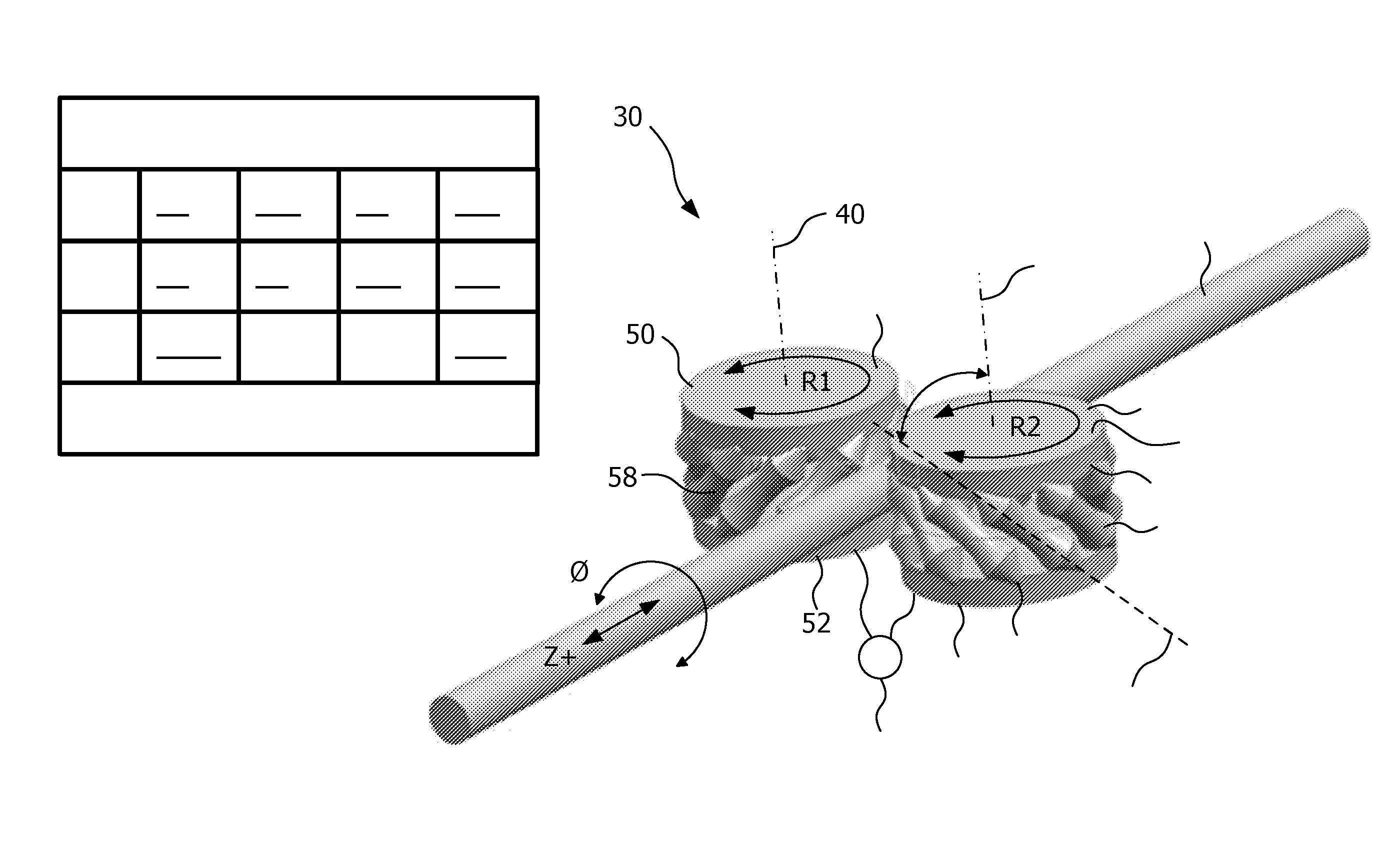
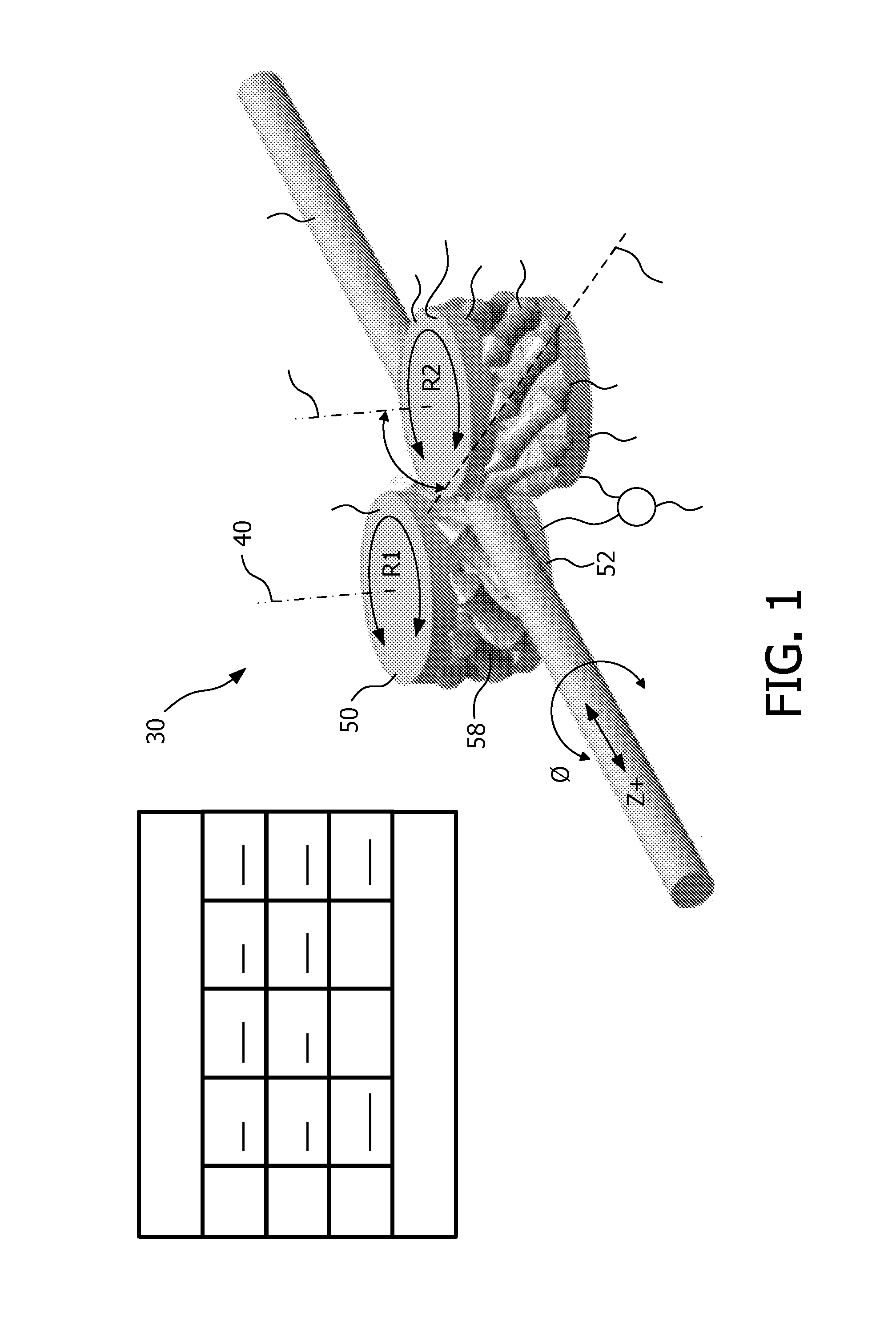
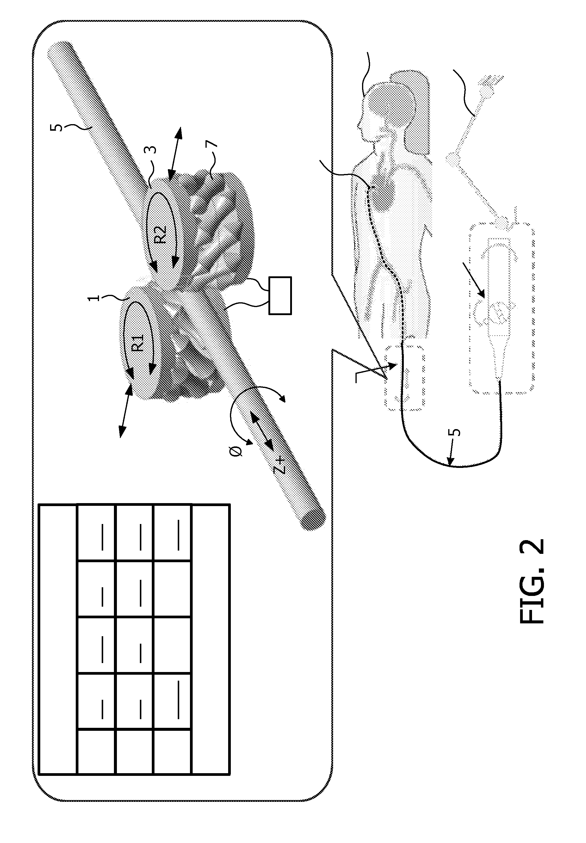
[0030]A first embodiment of the invention, shown in FIG. 1 is depicted in a perspective view. A steering system 30 comprises two radially oppositely arranged drive wheels 1; 3 for steering a tubular object 5 positioned between the drive wheels 1; 3. The drive wheels 1; 3 each have a wheel rotation axis 40; 42 and each include a plurality of rollers 7 distributed around the wheel rotation axis 40; 42. In this embodiment each wheel 1 has 12 rollers. ...


PUM


Abstract

A steering system (30) comprises two radially oppositely arranged drive wheels (1; 3) for steering a tubular object (5) positioned between the drive wheels (1; 3). The drive wheels (1; 3) each have a wheel rotation axis (40; 42) and each include a plurality of rollers (7) distributed around the wheel rotation axis (40; 42). The rollers (7) are rotatably arranged, each roller having a roller rotation axis (44) and an outer drive face (58) concavely vaulted in a direction corresponding to its roller rotation axis (44). The roller rotation axis (44) is obliquely oriented in relation to the wheel rotation axis (40; 42) and the rollers (7) of each drive wheel (1; 3) form together a steering periphery for the tubular object (5). The steering system enables continues rotation of a tubular object without danger that the object will lose the contact with the rollers. The steering system (30) may be incorporated in a catheter system which comprises a catheter (5).

Description

FIELD OF THE INVENTION[0001]The invention relates to a steering system comprising two radially oppositely arranged drive wheels for steering a tubular object positioned between the drive wheels.[0002]The invention also relates to a catheter system comprising such a steering system.BACKGROUND OF THE INVENTION[0003]An embodiment of such a steering system, viz. a catheter system, is disclosed in patent application US 2004 / 0254566 A1. The known system includes an apparatus comprising two rollers arranged parallel to each other and orthogonally to a catheter, which is gripped between these rollers. At least one of the rollers can be rotatably driven, and at least one of the said rollers is pressed elastically against the other to provide a frictional clamping of the interposed catheter. As a result of a roller's rotation in the clockwise or anti-clockwise direction the catheter moves longitudinally forwards or backwards respectively. Also, at least one of the two rollers can be axially m...

Claims


Application Information

Patent Timeline
Patent Type & Authority Applications(United States)
IPC IPC(8): A61M25/092B65H51/10
CPCA61B1/00147A61B8/12A61B8/42A61M25/09041A61B2019/2211A61M25/0113A61B19/2203A61B2034/301A61B34/30
Inventor BHAT, RAVINDRABOS, DENNIS ERWINRIJKEN, ANTONIUS MARIAPARDOEL, MICHEL GERARDUSIZMIT, SAIT
Owner KONINKLIJKE PHILIPS ELECTRONICS NV
Why Eureka
Try Eureka